
Fishman AG-094 - Manual de usuario

AG-Series
Passive Acoustic Guitar Pickup
Includes Installation Instructions for Models
AG-125
.125” (3.2 mm) Width • 2.125” String Spacing
AGX-125
.125” (3.2 mm) Width • 2.3125” String Spacing
AG-094
.094” (2.3 mm) Width • 2.125” String Spacing
AGX-094
.094” (2.3 mm) Width • 2.3125” String Spacing
Installation Guide
Installation Guide

Thank you for choosing the classic AG Series undersaddle pickup. Please read these instruc-
tions carefully. For technical assistance, contact Fishman Customer Support at 997788--998888--99666655
oorrtteecchh@@ffiisshhmmaann..ccoomm
The AG-Series is our original string-sensitive, piezo-ceramic undersaddle pickup. It provides
natural acoustic reproduction of your guitar with an explosive attack well-suited for percussive
playing styles. The pickup senses individual string vibrations with six fully shielded piezo ele-
ments. Installation is straight forward and you can plug the AG-Series pickup directly into an
instrument amplifier with great results. For improved performance we recommend one of our
dedicated outboard preamps.
Included with each AG pickup is our versatile Switchjack stereo endpin jack, which enables you
to wire up the AG pickup with another pickup or a microphone for outboard stereo blending
applications.
CHOOSING THE RIGHT MODEL TRANSDUCER
Before installation, be sure to select the right pickup for your instrument.
AG-125
E to E string spacing = 2.125" (54.0 mm)
Wire hole location = .234" (5.9mm) from clos-
est outside string
The AG-125 is suitable for most instruments
with string spacings from 2.075" (52.7 mm) to
2.175" (55.3 mm)
AGX-125
E to E string spacing = 2.3125" (58.7 mm)
Wire hole location is .234" (5.9mm) from clos-
est outside string
The AGX-125 is suitable for most 6 and 12-
string instruments with E to E string spacings
from 2.262" (57.4 mm) to 2.362" (59.9 mm)
NOTE: Custom string spacings are available
upon request.
WIDTH: .125" (3.2 mm)
HEIGHT: .048" (1.22 mm)
LENGTH: AG-125: 2.625" (66.67 mm)
AGX-125: 2.725" (69.22 mm)
AG-094
E to E string spacing = 2.125" (54.0 mm)
Wire hole location = .234" (5.9mm) from clos-
est outside string
The AG-094 is suitable for most instruments
with string spacings from 2.075" (52.7 mm) to
2.175" (55.3 mm)
AGX-094
E to E string spacing = 2.3125" (58.7 mm)
Wire hole location is .234" (5.9mm) from clos-
est outside string
The AGX-094 is suitable for most 6 and 12-
string instruments with E to E string spacings
from 2.262" (57.4 mm) to 2.362" (59.9 mm)
NOTE: Custom string spacings are available
upon request.
WIDTH: .094" (2.3 mm)
HEIGHT: .048" (1.22 mm)
LENGTH: AG-094: 2.625" (66.67 mm) /
AGX-094: 2.725" (69.22 mm)
2
2
AG Series -
AG Series - Passive Guitar Pickup
Passive Guitar Pickup

PREPARATION
Tools
• Caliper • Router with 1/8" (3mm) Straight Bit (single flute)
• 400 Grit Sandpaper or Scraper • Soldering Iron (30 watt max)
• Rosin Core Solder • Wire Strippers
• Masking Tape • X-Acto Saw
• Variable Speed Drill • Center Punch
• 1/8" Twist Drill • 15/32" Spade Bit Drill
• 1/2" Open End Wrench • 3/32" Allen Wrench
MECHANICAL FACTORS AFFECTING PICKUP PERFORMANCE
Break Angle
For the pickup to perform optimally, there should be a 20°(minimum) string break
angle across the back of the saddle. An adequate break angle can be realized by
"ramping" the string slots. In extreme cases, where the break angle is less than
20°and the saddle is so low that it is nearly flush with the top of the bridge, the
instrument probably requires a neck re-set. In these cases, re-setting the neck to a
higher angle will restore the saddle height and the string break angle required for
good pickup performance.
3
3
Installation Guide
Installation Guide
IIMMPPOORRTTAANNTT
Installation of the AG Series Acoustic Guitar Pickup requires fine woodworking & soldering
skills and should be performed only by a qualified repairman. Fishman Transducers will not be
responsible for any damages that may result from improper installation.
Please read these instructions carefully. For technical assistance, contact Fishman
If you are new to under saddle piezo installations, a comprehensive guide, The Finer Points of
Piezo Installation by Ken Parker, is available at www.fishman.com.
Handle the pickup carefully! Mishandling may result in ground hum or intermittent signal.
Fishman Transducers will not be responsible for any damages to the pickup that may occur
due to misuse or poor installation.
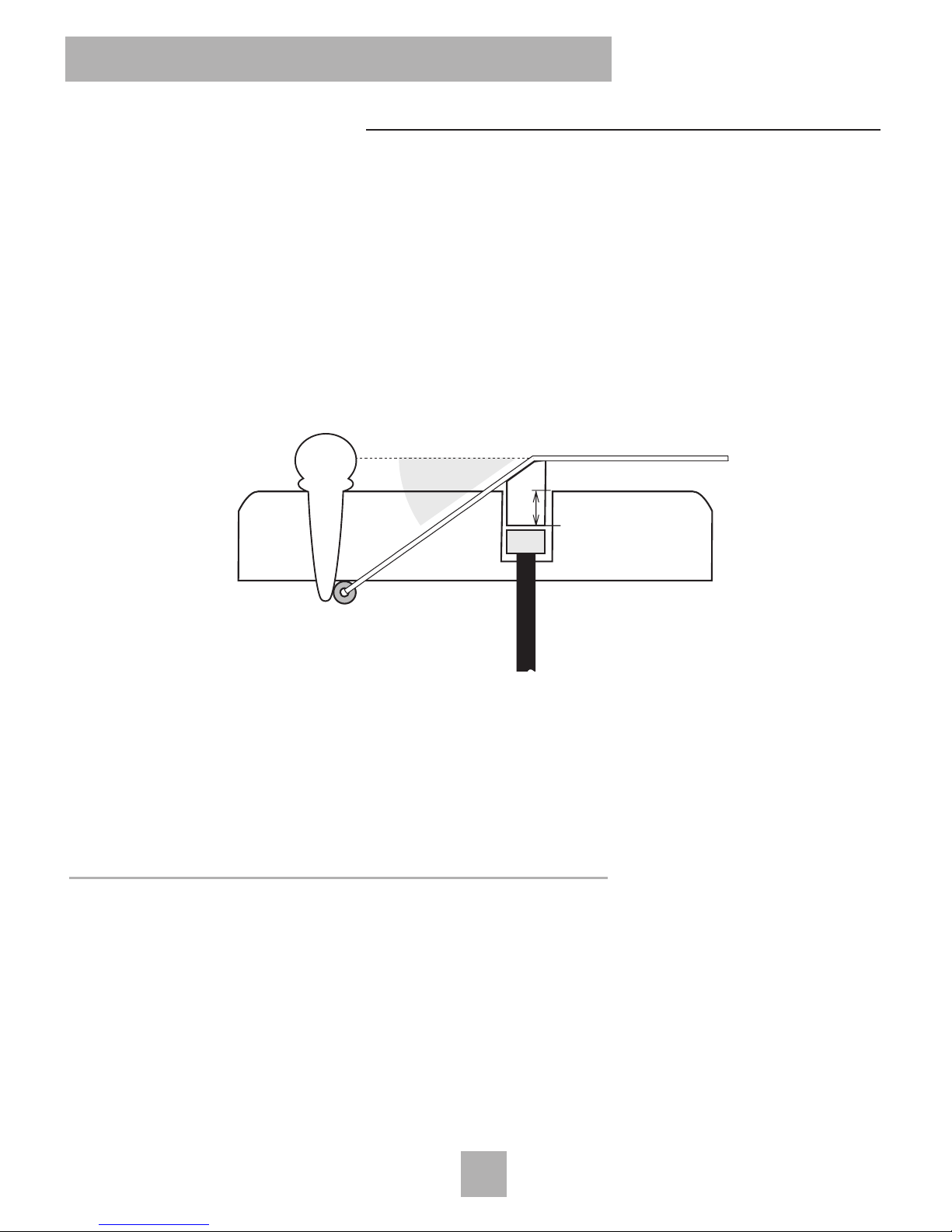
Mechanical Factors Affecting Pickup Performance - Continued
The 50/50 Rule
We have found that there is a critical relationship between the overall saddle height
and the bridge slot depth. For adequate mechanical coupling and pickup balance,
we recommend that the saddle slot depth (with pickup installed) measures no more
than 50% of the total height of the saddle. If the slot measures more than 50% of
the total height of the saddle, balance and/or output level may suffer. In these
cases, add a hardwood shim under the pickup. To determine the shim's thickness,
subtract ½ the total saddle height from the slot depth, then remove an equal amount
of material from the bottom of the saddle.
Exception to the 50/50 Rule: Pickups in bridges (especially Martin style 3/32" width) with
exceptionally steep string break angle will generally perform well, even if the saddle slot depth
measures more than 50% of the total saddle height.
PREPARATION
I • Prepare the Saddle Slot
A large percentage of string balance problems with undersaddle pickups can be
traced to an unevenly cut or warped saddle slot. Irregularities on the bottom or
sides of the slot can often prevent the saddle from uniformly pressurizing the pickup.
For this reason, we strongly recommend that before you install any undersaddle
pickup, re-mill an existing slot with a plunge router, jigged up in an appropriate slot
cutting fixture.
4
4
AG Series -
AG Series - Passive Guitar Pickup
Passive Guitar Pickup
NO MORE THAN 50%
RAMP
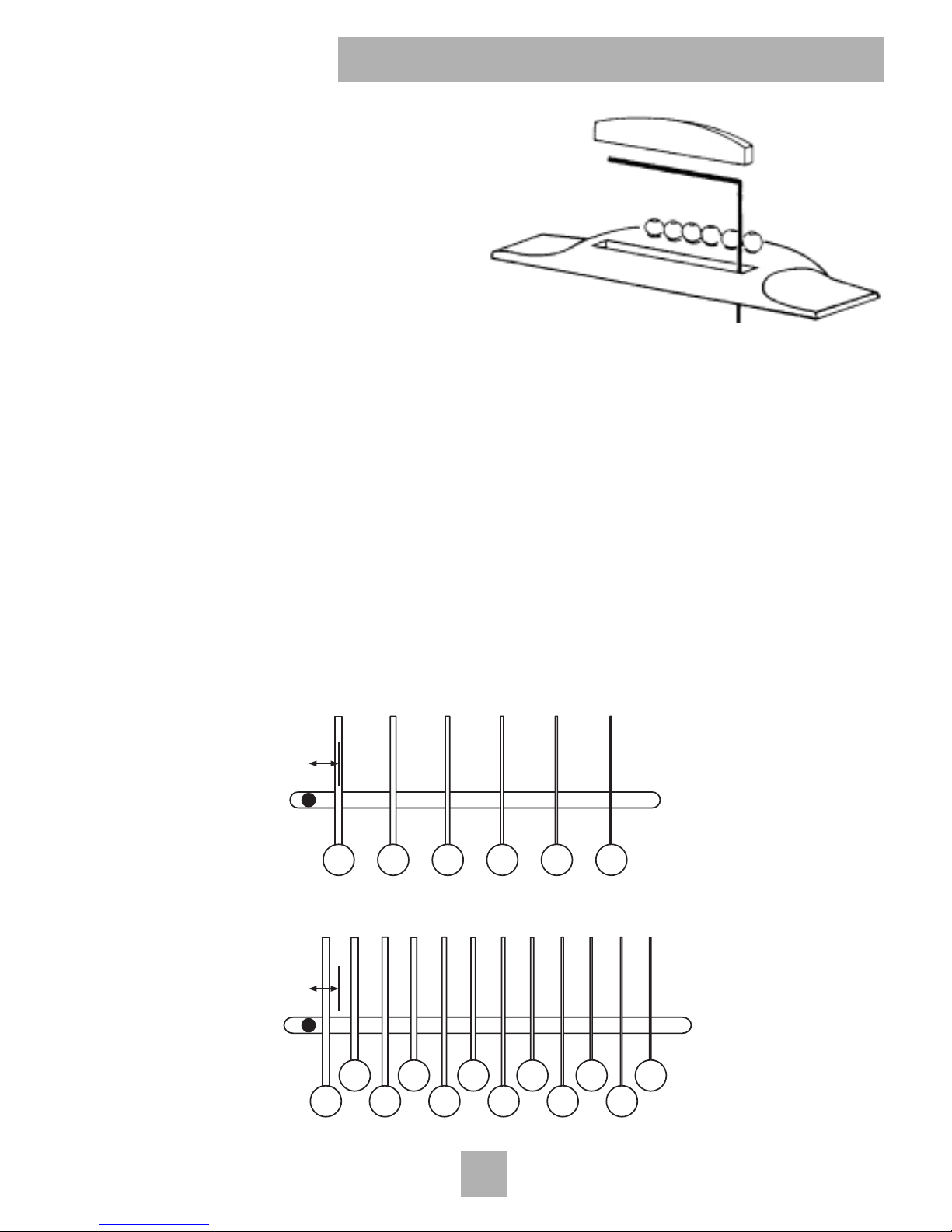
1. Rout a .125" (3.2 mm) or .094 (2.3 mm)
wide saddle slot.
2. Be certain that the bottom of the slot is
FLAT. Deepen an existing slot just
enough to obtain a clean, flat surface.
II • Locate the Wire Hole
The location of the wire hole is critical to the performance to the AG-125 / AG-094
as it determines the correct position of the piezo elements relative the strings.
1. Locate the center of the wire hole .234" (5.9 mm) from the closest outside string.
(Or center of the closest pair of outside strings for 12-string models.)
2. Mark the location where the wire will enter the saddle slot. Center the mark
between the walls (width) of the slot. Drill a .09375"(2.4mm) hole.
3. Clear wood chips and foreign materials from the saddle slot
4. Carefully insert the pickup. The wire must slip easily into the wire hole. The pick-
up must fit into the slot without friction or binding.
5
5
Installation Guide
Installation Guide
.234"
(5.9 mm)
.234"
(5.9 mm)

III • Prepare the Saddle
We highly recommend the Fishman Cleartone™ saddle for enhancing the perfor-
mance of the AG-Series pickup. We also suggest synthetic materials such as
Micarta or Corian as adequate substitutes. Organic materials such as bone or ivory
can not be recommended since these are not structurally as consistent as synthet-
ics and can produce poor string to string balance through the pickup.
1. Prepare a .125" or .094" wide saddle. Make sure the bottom of the saddle is
FLAT.
2. Remove only enough material from the width of the saddle to provide a sliding fit
in the slot. To test the fit, the saddle should slide easily in the slot, but should not
fall out when overturned. To maintain your current action, the new saddle must
be .048" shorter in height than your current saddle.
IV •Prepare the Endblock
There are two ways to widen the endpin hole to accept the endpin jack:
Slow and Safe
If you have the time, this is the preferred way to enlarge the endpin hole. Remove
the endpin and widen the hole to size with a 15/32'" (11.9mm) reamer, available in
the US & Canada through Stewart Macdonald, 800-848-2273, part #4323.
OR
Quick & Clean
The objective here is to drill out the hole with the endpin or other suitable plug in
place. You may remove a loose endpin and refasten it in the endblock with cyano-
acrylate glue before starting the procedure.
Note: We do not recommend this method for instruments with brittle orna-
mental veneers (ex: abalone) around the endblock.
6
6
AG Series -
AG Series - Passive Guitar Pickup
Passive Guitar Pickup

1. Apply masking tape around the endblock area to protect the instrument.
2. Locate an X-Acto saw blade 1/16" (1.6mm) away from the body and saw off the
endpin.
3. Centerpunch a guide hole in the center of the trimmed endpin.
4. Drill a 1/8" (3.2mm) pilot hole through the endblock.
5. Line up a 15/32" (11.9mm) Spade bit in the pilot hole and begin drilling. Maintain
a perpendicular plunge in relation to the instrument. Use steady (but not heavy)
pressure, especially as the drill exits inside the guitar.
6. To avoid damage to the instrument, let the drill come to a complete stop before
removing it from the hole.
V - Install the Pickup
1. Insert the pickup in the slot and then strip and tin the wire ends.
2. Unscrew the shielding cap on the jack to expose the solder terminals. Thread
the pickup wire through the shielding cap.
Gently bend back the strain relief/sleeve tab to gain better access to the Tip ter-
minal.
3. Solder the pickup "hot" wire to the Tip terminal, which is the shortest of the three
tabs.
Solder the pickup shield to the ground tab on the jack. Gently tighten the strain
relief.
4. Refasten the shielding cap to the jack.
7
7
Installation Guide
Installation Guide
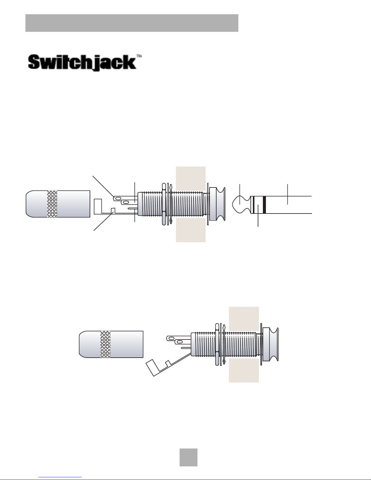
Wiring Options with the Fishman Switchjack
The Switchjack T-R-S-S (Tip/Ring/Sleeve/Switch) stereo switching endpin jack
allows simultaneous stereo operation and battery switching for active pickups. This
new configuration simplifies stereo wiring with many pickup combinations that were
once incompatible.
To gain better access to the Tip, Ring and Switch terminals, gently bend back the
Strain Relief/Sleeve tab, before you begin to solder.
Pages 9 & 10 illustrate the various wiring options made possible by the Switchjack.
8
8
AG Series -
AG Series - Passive Guitar Pickup
Passive Guitar Pickup
Shield
Tip
(Short Terminal)
Ring
TipGuitar Sleeve
1/4" Stereo Plug
Switch
(Long Terminal)
Ring
(Medium Terminal)

Pickup Signal
to Tip
Shield to
Sleeve
Pickup Signal
to Tip
2nd Pickup
to Ring
Common
Ground
Mono Wiring an AG Series Pickup
Mono Wiring an AG Series Pickup
Stereo Wiring a Second Pickup to an AG Series Pickup
Stereo Wiring a Second Pickup to an AG Series Pickup
9
9
Installation Guide
Installation Guide

10
10
AG Series -
AG Series - Passive Guitar Pickup
Passive Guitar Pickup
Negative Battery Wire
to Switch
Pickup Signal
to Tip
2nd Pickup
to Ring
Common
Ground
Stereo Wiring with an Active Pickup
Stereo Wiring with an Active Pickup
Common
Ground
Pickup Signal
to Tip
Microphone to Ring
Zener Diode
between Ring & Sleeve
Adding a Microphone to an AG Series Pickup
Adding a Microphone to an AG Series Pickup
Otros manuales para AG-094 -
1
Este manual sirve para los siguientes modelos
4
Tabla de contenidos
Otros manuales de Accesorios de Fishman

Fishman
Fishman ARCHTOP GUITAR PICKUP Manual de usuario

Fishman
Fishman AST POWERBRIDGE - DRILLING Manual de usuario

Fishman
Fishman CONCERT SERIES PICKUP Manual de usuario

Fishman
Fishman CONCERT PICKUPS Manual de usuario

Fishman
Fishman AG-094 - Manual de usuario

Fishman
Fishman ARCHTOP GUITAR PICKUP Manual de usuario

Fishman
Fishman Archtop Guitar Pickup Manual de usuario

Fishman
Fishman CLEARTONE Manual de usuario

Fishman
Fishman Powerbridge TSV Manual de usuario

Fishman
Fishman Music Pedal Manual de usuario


