First Watt F5 Manual de operación

First Watt model F5
Operation and Service Manual
So far, First Watt has made a few different amplifiers: Very different amplifiers.
Quite a few people have asked me for a regular sort of amplifier, you know the
kind you plug like any other, with some voltage gain and a real damping factor.
Amplifiers that have low distortion and noise, and will drive a 4 ohm load.
he last time people asked for that they got the Aleph J, which satisfied most
of those requirements. Single-ended Class A, the Aleph J is an easy-going
design which is happy driving 8 ohm loads with a warm, relaxed presentation.
By way of contrast, I present the F5 (taa-daa!), a push-pull Class A amplifier,
utilizing JFE s and MOSFE s in a very simple two stage complementary
circuit – a little bit like a complementary version of the Aleph J. But like all the
other First Watt amps so far – this one is different.
In many ways, it’s an ordinary topology - the basic circuit is found in numerous
preamp circuits and the odd power amplifier (Check out the Profet amp from
Selectronics). But the F5 is the product of numerous decisions that set it apart.
It has very wide bandwidth, DC to > 500 KHz.
No capacitors anywhere in the circuit. (except in the power supply, of course!)
It has a high input impedance – 100 Kohms, and a high damping factor (~60)
he distortion is very low, between .001% and .005% at 1 watt.
It’s very quiet, about 60 microvolts or so.
It will drive a 2 ohm load without burping, and 1 ohm without misbehaving.
Did I mention that it sounds terrific?
So enjoy. In addition to the normal owner’s manual information, I have
appended the original DIY F5 article which appeared in AudioXpress.
Nelson Pass 5/24/08

Setup
he initial setup of the amplifier is very straight-forward. Place the amplifier in
a well-ventilated location, as it draws about 180 watts during operation and
requires as much opportunity to cool itself as possible. You should be able to
put your hands on the heat sink during operation. If you can't do this for 5
seconds or so, they need more ventilation.
On the front panel there are two blue LED lights, one for each channel,
indicating power to the channel. On the rear panel you will find a pair of RCA
inputs, speaker outputs, a fuse holder, an AC power receptacle, and on/off
switch.
he label will indicate a serial number and also what AC line voltage the
amplifier is set for. If the voltage is 120 VAC, then the fuse value will be a 3AG
slow blow fuse rated at 2.5 amps. If the voltage is 240 VAC, then the fuse will
be rated at 1.25 amps. Do not substitute a larger value fuse. Contact First
Watt if you have any questions.
I'm assuming that you know how to attach the speaker cables to the 5 way
output connectors provided. Please make all the connections with the
amplifier power switch in the OFF position.
For two channel operation, input signal is connected to the RCA inputs. he
output connections to the loudspeakers are made through the gold plated
brass 5 way connectors. he red (top) connection is positive and the black
(bottom) is negative. In this amplifier the black banded output connectors are
connected directly to signal ground.
A caveat is in order here – this is a very wide band amplifier with a high input
impedance. In order to prevent the output voltage from bleeding back to the
input at very high frequencies (thus making a fine power oscillator), keep the
input and output cables separate, and don’t externally connect the speaker
ground to the input ground. Good ground shielding on the input cables is
important, and caution is called for in using Litz and other specially low
inductance / high capacitance cables. I have not seen a specific example of a
problem, but historically it is to be expected when an amplifier’s bandwidth
exceeds 200 KHz. If the amp makes funny noises, runs extra hot, or blows
fuses, this might be an indicator of such an issue.
If you have any questions, just drop me an email: [email protected]

With everything connected up and the source equipment powered up first, you
can proceed to turn on the power switch to the amplifier. urn-on and turn-off
thumps and noise are small in this amplifier, and should not present any
hazard to delicate drivers.
At this point you should be able to listen to music. his amplifier has less gain
than most (15 dB), but at 25 watts, it’s not likely to need it. If you need to turn
the gain up on your preamp, then do so. If you can't get enough gain, then you
are probably using either the wrong speaker or the wrong amplifier. alk to
your dealer if this is the case.
he power supply of the amplifier is isolated from the chassis and AC earth
ground by a thermistor which connects the circuit ground to the chassis and
earth ground. his helps to prevent ground loops, but the thermistor stands by
to conduct AC line voltage to ground until the fuse blows in case of transformer
or other such failure.
he input impedance is 100 Kohms, and the input capacitance is very low, so
you should find it easy to drive with tube equipment if you like. he amplifier is
largely indifferent to the source impedance of your preamp, so a high source
impedance is not a problem.
he amplifier requires about 1 hour of operation to reach normal operating
temperature, and this warm-up time is appropriate for the most critical
listening, but is not otherwise an issue. he amplifier’s final adjustments were
made after a 2 hours, and the performance difference between that and cold
operation is significant.
I do not personally see a reason to run the amplifier all the time, but you can
do that if you want to. he power supply capacitors are likely to last about 15
years or so, and while they will slowly dry out just sitting there, they will have a
shorter life span with the amplifier running constantly. Also, at 180 watts it
makes economic sense to shut the amplifier off if you aren’t planning on using
it for the rest of the day.
Again, the heat sinks on this amplifier run fairly hot, and you want to make sure
that they get adequate ventilation. hey will run at around 25 degrees C.
above the ambient temperature, which puts them around 50 degrees in the
average listening room. At this temperature you should be able to put your
hand on them for about 5 to 10 seconds or so.

Now the following is for your protection –
Do not defeat the AC line Earth ground connection on the amplifier
power cord. It provides an extra barrier to prevent potential shock
hazard.
Do not replace the fuse with a type other than specified.
Do not operate the amplifier outside in the weather, or in and around
water or anything resembling water. If you spill a drink in the
amplifier or if your dog/cat/child urinates on it, turn it off immediately,
unplug it, and do not operate it until cleaned by a qualified
technician.
If something gets loose or rattles around inside or smells funny, or if
you can’t touch the heat sinks for 5 seconds or so, then turn it off,
unplug it from the wall, and contact First Watt.
here are no user serviceable parts inside. Do not open the
amplifier, and if you do anyway, don’t operate it with the cover off.
here are hazardous voltages inside. If you need to change the
operating AC voltage, contact First Watt.
If you have a problem, contact First Watt. We are much happier
helping you solve problems so that we can be certain that it’s done
properly. If you are far away and don’t want to ship the product for
repair, we will assist your technician with information and parts.
Contact: www.Firstwatt.com [email protected]

Summary of the nominal specifications:
Measured at 120 V AC with a 25 ohm source and an 8 ohm load:
Distortion @ 1 watt .001% to .005% @ 1 KHz
Input Impedance 101 Kohm
Damping Factor 60
Output power stereo 8 ohms 25 watts @ 1% HD, 1KHz
Voltage Gain 15.3 dB
Maximum unclipped output +/-20 Volts
Maximum output current 10 amps
Frequency response - .0 dB @ DC, -3 dB @ ~ 1 megaHertz
Noise ~60 uV unweighted, 20-20 KHz
Power consumption 180 watts
Fuse 3AG slow blow type, 2.5 Amp for 120VAC
1.25 Amp for 240 VAC
Warranty: Parts and labor for 3 years, not covering shipping costs or any sort
of consequential damages. Warranty coverage is voided for modified
products, and repair of modified products is at our discretion.
Copyright 2008 General Amplifier
General Amplifier Inc.
PO BOX 7607
RENO NV 89510-7607
www.firstwatt.com

F5 Power mplifier ( s printed in udioXpress, May 08)
Nelson Pass 1/31/08
Intro
As many of you may know, First Watt is dedicated to exploring the performance quality of
small simple power amplifiers. Over the past four years, five such amplifiers have been
designed as concept pieces and produced in limited quantities.
he F1 and F2 explored the possibilities of current source operation with single-stage Class
A circuits and no feedback. he Aleph J used JFE devices for the front end of a two stage
single-ended Class A amplifier. he F3 achieved very low distortion using power JFE s in
a single-stage, single-ended Class A circuit. he F4 demonstrated that an amplifier did not
necessarily require voltage gain to be useful.
You can follow the progression at www.firstwatt.com
Here is the F5. We want to further push the performance boundaries of simple little
amplifiers with a FE two-stage Class A push-pull design.
Quickie Tutorial on FET mplifiers
One of the aims of these articles is to get people to build amplifiers, so here is some tutorial
material to get beginners going. I have written up some of this material before (“ he A75”,
Audio Amateur 4/1992), but that was 15 years ago, and maybe it will be helpful to repeat
bits of it. All 31 years worth can be found at www.passdiy.com and related links.
I’m assuming that you understand the concepts of voltage, current, and resistance. If you
already know how a FE works, you can skip ahead.
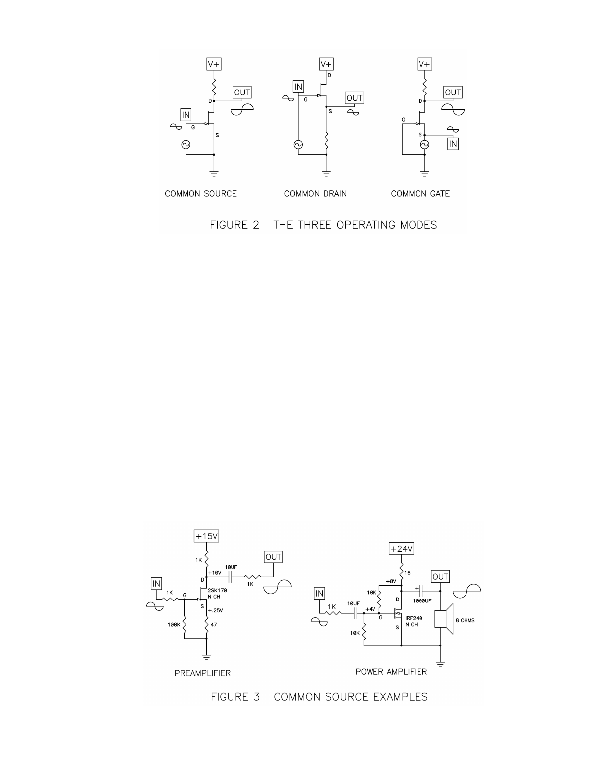
Figure 1 shows an N channel FE , a quantum mechanical black box with three connections.
his device is meant to function as a valve, a little bit like a water faucet. In this picture, the
Drain (D) of the FE is attached to an electrical power supply, analogous to the pressurized
water supply on the other side of the faucet. You can imagine the pipe as wire, and the tank
of water as a battery or even a charged-up capacitor.

o continue the metaphor, the voltage of the supply is the water pressure, and the water
flowing from the supply is the electrical current. he Source (S) connection of the FE is
the output of the faucet. he Gate (G) of the FE is the control pin, and like the handle on
the faucet, it controls the amount of electrical current through the FE from the Drain to the
Source. For the FE , this control is a function of the relative voltage between the Gate and
Source pins. For an N channel FE , raising the Gate positively with respect to Source
increases the current flow.
Yes, I know some of you are thinking that maybe the Source should be on top and the Drain
on the bottom, but they’re not. You might not want to call a quantum mechanic if your
plumbing stops up.
he idea that the current going through FE transistor is controlled by the voltage between
the Gate and the Source pins remains the key idea, and if you have that firmly fixed, we can
leave the waterworks metaphor behind.
FE S come in different types. here are two polarities, N channel and P channel. here
are different voltage, current, and power ratings, and different semiconductor processes
resulting in JFE s and MOSFE s. In all of them, the current from the Drain to Source is
controlled by the voltage between Gate and Source.
A FE is a three pin device, and there are three ways to amplify with them. Figure 2
illustrates these with an N channel FE :
Common-Source (CS) is the connection which can give us both voltage and current gain in
a circuit. he input voltage (shown as a little graphical sine wave) goes to the Gate, and the
output is taken from the Drain and appears across a resistor between the Drain and the
supply voltage. he Source is grounded, and doesn’t show a signal voltage, and that’s why
it’s called Common-Source. Note that the output voltage is inverted in phase from the input
voltage.
Common-Drain (CD) gives current gain only, and is also known as Source follower,
because the output voltage across the Source resistor is nearly identical to the input voltage
at the Gate. While the Drain is usually attached to a DC voltage value, the AC voltage is
ideally zero, and so it is called Common-Drain.
Common-Gate gives non-inverted voltage gain only, with the input signal going into the
Source and coming out the Drain. he Gate is grounded.
Figure 2 only shows what happens to AC signals, but it doesn’t illustrate the DC voltage and
current values that the FE s need in order to operate. hese DC values are often referred
to as the bias of the device, and you will hear that word a lot with respect to amplifiers.
he optimum bias values vary by the device and the needs of the circuit. In general, to
function as an amplifier, the FE needs to have a least a few volts between the Drain and
the Source. If the FE is an N channel type, the Drain must be at least a few volts positive
with respect to Source. If it’s a P channel type, the drain must be negative with respect to
Source.
In addition, the Gate of the FE must be placed at a DC value relative to the Source so that
the current and voltage of the FE is positioned in the linear region between the extremes of
voltage and current – somewhere between all the way on and all the way off. It is in the
middle ground where the distortion is low. Generally for N channel JFE s, it is with the
Gate voltage at 0 or slightly negative with respect to the Source, and for N channel
MOSFE s the gate voltage is a couple volts positive. One of the important functions of a
circuit is to set up the DC conditions of gain stages so that the devices have stable
operation in this region. For every amplifying circuit, there will be a “sweet spot” of voltage
and current which will give the best overall performance.
Figure three shows some examples of real circuits that illustrate simple Common-Source
amplifiers and the bias voltages and currents that would be typical for them. You can build
both of these circuits and they will work.
On the left you see an example of a simple preamplifier stage with a gain of roughly 10
times (20 dB). he JFE is self biased in this circuit: With 5 mA going through the JFE ,

the gate needs to be at about -.25V with respect to the Source. We put 47 ohms in series
with the Source, raising its voltage to +.25V and this conveniently allows us to bias the Gate
at 0V DC, or Ground.
On the right, we have a power MOSFE set up as a simple power amplifier, intended to
deliver about 1 watt into an 8 ohm loudspeaker. he 16 ohm power resistor performs as a
current source to the circuit, and the two 10 Kohm resistors on the input set the DC value for
the Gate to about 4 volts get it to conduct a 1 amp bias current. For a more powerful
version of this, see Zen Variations #1 (AudioXpress, March 2002)
Figure four shows some real Common-Drain amplifiers, a line-level buffer which can be
used in active filters, and a headphone amplifier. In both cases there is no voltage gain in
the amplifier, but there is current gain. hey both have high input impedance and low
output impedance.
Common-Gate operation is encountered less often, usually found in “cascode” connection
with another device. Discussions of cascoding with good examples are found in Zen
Variations 8 and 9 (AudioXpress January 2006, May 2006) and also the article “Cascode
Amplifiers” originally published in Audio Magazine, March 1978.
Simplified F5 Circuit
Figure 5 shows the simplest imaginable version possible of the F5. he topology is familiar;
a two-stage conjugate-complementary circuit using two JFE transistors for the input
amplification and two power Mosfet devices for the output.

JFE s Q1 and Q2 form a complementary Common-Source stage, with the input appearing
at their Gates and output at their Drains. he JFE S are Class A self-biased at about 6 mA,
and so a current I1 comes out of their Drain connections and creates a voltage of about 3.6
volts across R3 and R4, whose values are about 600 ohms. his 3.6V DC value is
necessary to bias the power MOSFE s Q3 and Q4 into conduction. he voltage gain of Q1
and Q2 appears across each of these resistors for a gain of about 10 each.
he gain of 10 for the input stage comes from the ratio of the 600 ohms divided by the
apparent resistance from the Source to Ground, which is roughly 60 ohms. his 60 ohm
number comes from the inverse of the JFE ’s transconductance plus the 10 ohm actual
resistor. he transconductance for a JFE is the ratio of current change against input
voltage change. he gain of this part is typically 0.02 Siemens, or .02 amps per control volt,
and if you invert that you get 50 ohms (R = V/I). So it looks as if there is 50 ohms inside the
part (although there isn’t), and to that we add the 10 ohms of real resistor to get 60 ohms.
Q3 and Q4 do the heavy lifting in this circuit, providing the large output current needed to
drive the loudspeaker. he DC voltage appearing from the Gate to Source of these devices
is about 3.6 volts, and this biases the MOSFE s to about 1.3 amps.
For this sort of circuit, a 1.3 amp bias means that the amplifier will operate Class A to 2.6
amps of output current. o understand this, imagine a condition where Q3 and Q4 are
idling at 1.3 amps, so that all the current is going from the V+ voltage rail to the V- voltage
rail, and none is going through the loudspeaker.
When a positive voltage appears at the Gates of Q1 and Q2, it makes the current through
Q1 increase and the current through Q2 decrease. he resulting voltages across R3 and
Tabla de contenidos
Otros manuales de Amplificador de First Watt


