Fireray 3000 Manual de usuario

End To End
Optical Beam Smoke Detector
User Guide
EN
ocument Number: 0044-047-01-EN

Contents:
1. Installation
2. Commissioning
3. In Use
4. Maintenance and Troubleshooting
5. isplay and Indicators
6. User Menu
7. Engineering Menu
8. Specification
9. Approval Information
Page:
3
6
14
17
18
19
20
24
25
2

3
1. Installation
1.1 Mounting and ositioning
>30cm
>30cm
Transmitter
(Clear Lens)
Receiver
(Black Lens)
Power
Supply Unit Controller
5 - 120m
•IM ORTANT NOTE: The infrared beam path MUST be kept clear of obstructions at all times!
Failure to comply may result in the system initiating a Fire or Fault signal.
• Check the beam spacing against local regulations
• Ensure clear line of sight from Receiver to Transmitter
• Mount on solid surfaces (structural wall or girder) and ensure fixing is rigid
• Position beam as high as possible, but with a minimum distance of 30cm from Receiver/Transmitter to ceiling
• For installations complying with UL 268/NFPA 72, the maximum distance of Transmitter and Receiver from the
ceiling must be 10% of the distance between floor and ceiling
• Mount Receiver and Transmitter directly opposite each other
• o NOT position where personnel or objects can enter the beam path

4
• Note 1: This component is the fire resistor. Its value is specified by the Fire Control Panel manufacturer. For U.S.
installations it is typically a short circuit
• ALWAYS use a separate 2-core cable for each Receiver head
• CAUTION: For system monitoring - o not use looped wire under any terminals. Break wire run to provide
monitoring of connections
• Components not supplied:
• Schottky iode - Typically 60V, 1A (UL-rated for installations conforming to NFPA 72)
• End Of Line ('EOL') component - supplied by Fire Control Panel manufacturer
• Fire Resistor not supplied
• After installation, check operation of Fire and Fault connection on Fire Panel
1.2 Wiring Diagram
RECEIVER 1
OUTPUT
+ -
RECEIVER 2
OUTPUT
+-
TRANSMITTER
SUPPLY
+-
TRANSMITTER
SUPPLY
+-
12V to 36V C
RECEIVER 1
FIRE
N/O COM N/C
RECEIVER 1
FAULT
N/O COM N/C
RECEIVER 2
FIRE
N/O COM N/C
RECEIVER 2
FAULT
N/O COM N/C
RECEIVER 1
FIRE
N/O COM N/C
RECEIVER 1
FAULT
N/O COM N/C
RECEIVER 2
FIRE
N/O COM N/C
RECEIVER 2
FAULT
N/O COM N/C
ZONE -
ZONE +
see note 1
see note 1
EOL
see note 1
EOL
see note 1
EOL
EXTERNAL
RESET
EXTERNAL
RESET
ZONE 1 -
ZONE 1 +
ZONE 2 -
ZONE 2 +
SUPPLY -
SUPPLY +
For connection of both Receivers to one zone:
For connection of Receivers to individual zones:
5
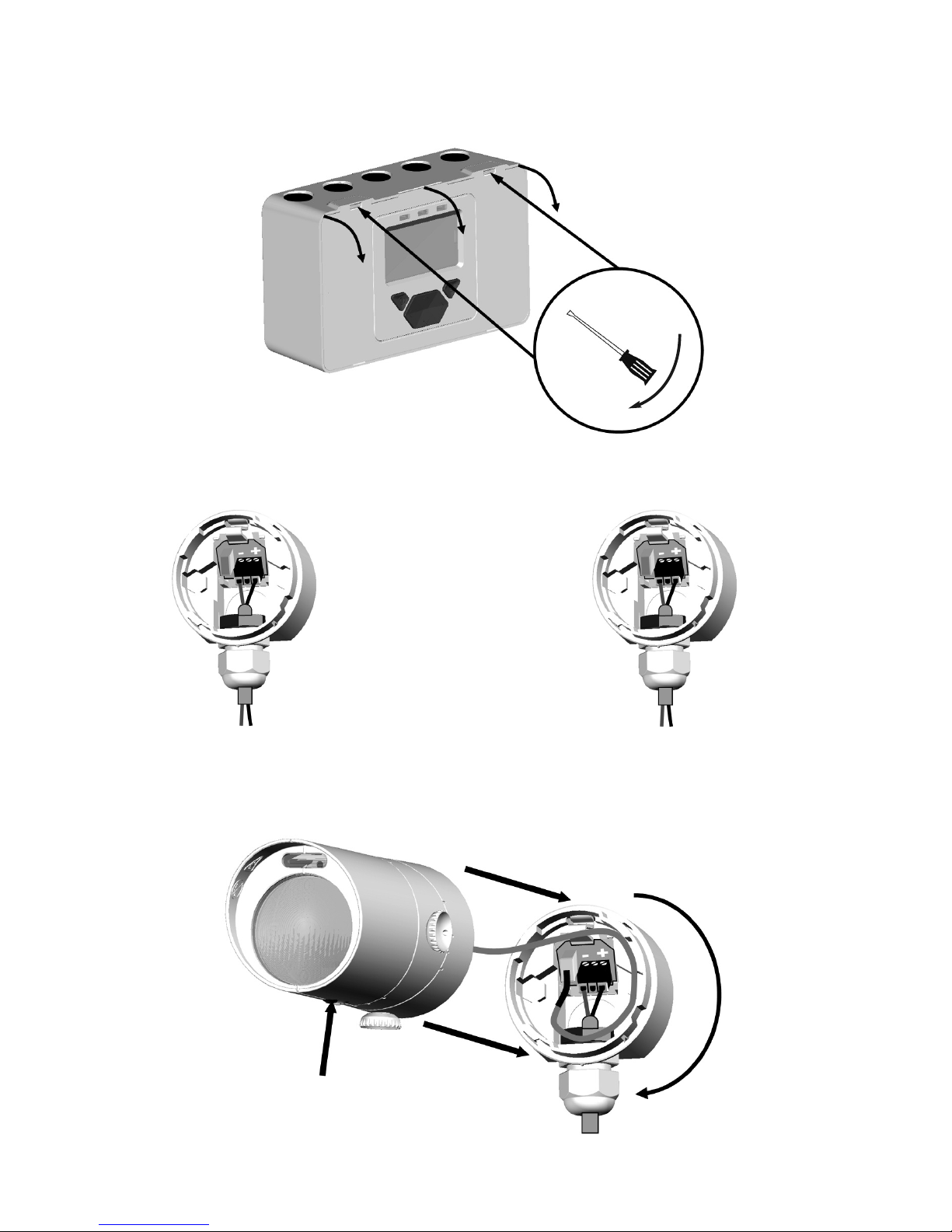
1.3 Fitting the roduct
LE indicator must face
downward
- +
TO RECEIVER
OUTPUT ON
CONTROLLER
BOAR
RECEIVER:
- +
TO
12 to 36V C OR
SUPPLY ON
CONTROLLER
BOAR
TRANSMITTER:

6
NOTE: One System Controller can be used to control and monitor up to two Receiver heads. The ‘#’
symbol in this guide is used to represent the number of the Receiver currently selected (1 or 2).
Apply Power to Controller,
Receiver(s) & Transmitter
3 seconds
2. Commissioning
2.1 Apply ower
• Commissioned System:
• Communications fault, or no Receiver connected:
• Receivers are not found (normal at this stage):
• Receivers have been found but not commissioned:

7
efault Pass Code: 1234
To enter PASS CO E SCREEN in USER MENU
Change digit
Move between digits
Accept
2.2 Enter ass Code to Access Engineering Menu
• An incorrect Pass Code will return the display to the Pass Code entry screen
• A partial passcode (ie. with dashes in it) will not be accepted
• Three incorrect attempts will lock access for three minutes

• Press tick to enable ‘Found’ Receivers
• Any unused Receiver channels are switched off
8
• Perform 'Find' during initial installation, or when adding or removing Receivers
2.3 Finding Receivers
As each Receiver is
"Found" the relevant
receiver number appears
here
This will be the number of
Receivers found
To re-scan if the number is incorrect

9
• All Receivers need to be aligned separately
• The following sections in this User Guide explain how to align individual Receivers
2.4 Select Receiver to be Accessed

• The LASER in the Receiver head is used to align the Receiver with the Transmitter.
• The LASER can be activated using the button on the Receiver head whilst in Engineering Menu, or via the
LASER icon in the ENGINEERING MENU as shown below.
• Move the LASER as close to the Transmitter as possible, by moving the Receiver’s thumbwheels
• The system will signal Fault while in this mode
10
2.5 LASER Targeting
This LASER TIMEOUT
value (MIN=1 min.;
MAX=59 mins.) may be
incremented or
decremented in 1 min.
steps by using:
Countdown Elapsed
LASER RA IATION - AVOI
IRECT EYE EXPOSURE
POWER OUTPUT < 5mW
CLASS IIIa LASER
Wavelength 630 - 680 nm
ANGER
If it is not possible to see the LASER because of the installation environment (for example, if there is high ambient
light) then mechanically align the Receiver by eye so that it is pointing at the Transmitter.
Tabla de contenidos
Otros manuales de Detector de humo de Fireray


Manuales populares de Detector de humo de otras marcas


System Sensor
System Sensor DH500ACDC Manual de usuario

Resolution Products
Resolution Products RE612 CryptiX Manual de usuario

First Alert
First Alert PC900V Manual de usuario

Eminent
Eminent EM6590 E-Domotica Manual de usuario

Ei Electronics
Ei Electronics Ei Ei168RC Manual de usuario

Carrier
Carrier Kidde Quell Q301 Manual de usuario


