Fiplex nanoSAW Series Manual de usuario

n
ano
SAW
Series
Re
peater
User’s Manual
November 2009

UM-0101-01.09 – November 2009
II
Document History
Description
Revision
Date Issued
Preliminary release for early field trials 0.0 September 10
th
, 2009
Preliminary release, screenshots updated 1.0 November 1
st
, 2009

UM-0101-01.09 – November 2009
III
About this manual
This manual describes installation, commissioning, usage, function, operation and maintenance of Fiplex
nanoSAW series repeater and Fiplex portable Operational and Maintenance Software (pFOMS). The first
part of the manual describes the repeater hardware and the second part describes the software.
Hardware and software mentioned in this manual are subjected to continuous development and improvement.
Consequently, there may be minor discrepancies between the information in the manual and the performance
and design of the hardware and software. Specifications, dimensions and other statements mentioned in this
manual are subject to change without notice.
This manual or parts of it may not be reproduced without the written permission of Fiplex Europe SL.
Infringements will be prosecuted. All rights reserved.
Copyright © Fiplex Communications Inc, USA, 2009.

UM-0101-01.09 – November 2009
IV
ontents
Abbreviations ..................................................................................................................................V
Part 1 HARDWARE......................................................................................................................... 1
1. Safety.......................................................................................................................................1
FCC Radiation Hazard Warning....................................................................................................1
R&TTE Compliance Statement.....................................................................................................1
Disposal of Electric and Electronic Waste.....................................................................................1
2. Installation ................................................................................................................................2
Sitting the repeater .......................................................................................................................2
Mounting.......................................................................................................................................2
3. Commissioning.........................................................................................................................3
Connection...................................................................................................................................3
Starting operation.........................................................................................................................4
Status Indicators...........................................................................................................................5
Automatic Gain Control (AGC)......................................................................................................7
Overload Protection......................................................................................................................7
Downlink Signal Indicator .............................................................................................................7
Laboratory Measurements............................................................................................................7
Part 2 SOFTWARE ......................................................................................................................... 8
4. Installation ................................................................................................................................8
5. Overview.................................................................................................................................14
General Tabsheet.......................................................................................................................14
Status tabsheet...........................................................................................................................15
Configuration..............................................................................................................................16

UM-0101-01.09 – November 2009
V
Abbreviations
AGC Automatic Gain Control
AMPS Advanced Mobile Phone Service
ARFCN Absolute Radio Frequency Channel Number
BCCH Broadcast Control Channel (GSM broadcast channel time slot)
BS Base Station, BS antenna = towards the base station
CDMA Code Division Multiple Access
DC Direct Current
DCS Digital Communication System (same as PCN)
DL Downlink signal direction (from base station via repeater to mobile station)
DPLX Duplex filter
EEPROM Electrical Erasable Programmable Read Only Memory
EGSM Extended Global System for Mobile communication
ETACS Extended Total Access Communication System
ETSI European Telecommunications Standard Institute
GSM Global System for Mobile communication
HW Hardware
LED Light Emitting Diode
LNA Low Noise Amplifier, uplink and downlink
MS Mobile Station, MS antenna = towards the mobile station
OMS Operation and Maintenance System
OL Overload
PA Power Amplifier
PCN Personal Communication Network (same as DCS)
PCS Personal Communication System
pFOMS Portable Fiplex Operation and Maintenance Software
PS Power Supply
RF Radio Frequency
RSSI Received Signal Strength Indication
SW Software
TDMA Time Division Multiple Access
UL Uplink signal direction (from mobile station via repeater to base station)
WEEE Waste of Electric and Electronic Equipment

UM-0101-01.09 – November 2009 1
Part 1 HARDWARE
1. Safety
Any personnel involved in installation, operation or service of Fiplex repeaters must understand
and obey the following:
Any repeater, including this repeater, will generate radio signals and thereby give rise to
electromagnetic fields that may be hazardous to the health of any person who is extensively
exposed to the signals at the immediate proximity of the repeater and the repeater antennas.
FCC Radiation Hazard Warning
To comply with FCC RF exposure requirements in Section 1.1307 and 2.1091 of FCC Rules, the
antenna used for this transmitter must be fixed-mounted on outdoor permanent structures with a
separation distance of at least 2 meter from all persons.
R&TTE Compliance Statement
This equipment complies with the appropriate essential requirements of Article 3 of the R&TTE
Directive 1999/5/EC.
BTS chassis, Repeater, feeders, donor antenna, service antenna/s and auxiliary equipment (splitters, tabs,
.etc) are required to be bonded to protective grounding using the bonding stud or screw provided
with each unit.
Static electricity means no risk of personal injury but it can severely damage essential parts of
the repeater, if not handled carefully.
Parts on the printed circuit boards as well as other parts in the repeater are sensitive to
electrostatic discharge.
Never touch printed circuit boards or uninsulated conductor surfaces unless absolutely
necessary.
If you must handle printed circuit boards or uninsulated conductor surfaces, use ESD protective
equipment, or first touch the repeater chassis with your hand and then do not move your feet on
the floor.
Never let your clothes touch printed circuit boards or uninsulated conductor surfaces.
Disposal of Electric and Electronic Waste
Pursuant to the WEEE EU Directive electronic and electrical waste must not be disposed of with unsorted
waste. Please contact your local recycling authority for disposal of this product.

UM-0101-01.09 – November 2009
2
2. Installation
Sitting the repeater
Fiplex nanoSAW family of repeaters is designed for indoor use.
If repeater needs to be mounted outdoors, weather proof cabinet should be provided in order to
preserve weather tightness.
Mounting
nanoSAW is ready for wall mount using four fixing screws.
Figure 1
Figure 1 shows holes pattern for fixing screws.
UM-0101-01.09 – November 2009
3
3. ommissioning
Connection
1. Connect service antenna (“TO MOBILE” port) and donor antenna (“TO BASE” port) coaxial
cables. SMA type female connectors are used in the repeater.
2. Once RF ports of the repeater are properly loaded connect the DC plug from power supply to
nanoSAW DC input.
The repeater powers on when power supply is connected to the AC line, and nanoSAW is
properly feed with DC voltage. Blue led labelled “PWR ON” must be on, under normal power
conditions.
Figure 2
Figure 2 shows DC input plug position.

UM-0101-01.09 – November 2009
4
Starting operation
Prior to the following steps refer to section 2 of this manual in order to properly install pFOMS.
1. Setup desired filter configuration using pFOMS (only for programmable band selective and
programmable channel selective models).
In programmable band selective repeaters user must set up start and stop frequency.
In programmable channel selective user must set up center frequency, nanoSAW repeaters are
a special case of programmable selective repeater, where number of channels is equal to one.
For both types of repeaters user could set up start, stop or center frequency either using
absolute values (in MHz) or using ARFCN.
For fixed bandwidth repeaters this feature will not allow user to make changes, so, skip this step
for fixed bandwidth models.
2. Setup desired operating gain using pFOMS. UL and DL chain are independent, so both
values must be set.
For nominal gain of the repeater these values must be set to zero.
Figure 3
Figure 3 shows how to set up manual attenuation values.

UM-0101-01.09 – November 2009
5
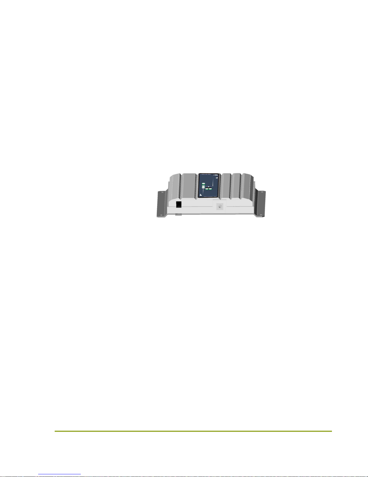
Status Indicators
There is an indicator panel located at the front of the repeater. This led panel works as a status
monitor, in order to advice different operational conditions of the repeater.
1. Power indicator
Every time the repeater is plugged to DC power supply, and under normal conditions of
operation, led labelled PWR ON will be ON.
Figure 4
Figure 4 shows PWR ON led location.
2. Automatic Gain Control Indicator
When Automatic Gain Control circuitry is active led labelled AGC UL and/or AGC DL will be ON.
Please see Automatic Gain Control for further functional explanation.
Figure 5
Figure 5 shows AGC DL led active, this is only for example purposes.
3. Overload Indicator
When Overload circuitry is active led labelled OV DL or OL UL will be ON.
Please see Overload Protection for further functional description.
Figure 6
Figure 6 shows OL DL led active, this is only for example purposes.
Tabla de contenidos
Otros manuales de Reloj de repetición de Fiplex


