
FIP FLS M9.10 Manual de usuario

1
FLS M9.10
DUAL-PARAMETER ANALOG
MONITOR & TRANSMITTER
SAFETY INSTRUCTIONS
PACKING LIST
General Statements
• Do not install and service the product without following the Instruction
Manual
• This item is designed to be connected to other instruments which can be
hazardous if used improperly. Read and follow all associated instrument
manuals before using with it
• Product installation and wiring connections should only be performed by
qualied sta
• Do not modify product construction
Installation and Commissioning Statements
• Remove power to the instrument before wiring input and output connections
• Do not exceed maximum specications using the instrument
• To clean the unit, use only chemical compatible products
Please verify that the product is complete and without any damage.
The following items must be included:
• M9.10 Dual Analog Input Monitor and Transmitter
• Instruction Manual for M9.10 Dual Analog Input Monitor and Transmitter

2
DESCRIPTION
CONNECTIONS TO INSTRUMENTS
The new FLS M9.10 is a powerful monitor designed to manage analog and
frequency signals (or two analog signals) from every types of device which
provide a 4-20mA or a frequency output. M9.10 is equipped with a wide full
graphic display 4” which shows measured values clearly and a lot of other
useful information. Moreover, due to a multicolor display plus a powerful
backlight, measurement status can be determined easily from afar also.
A tutorial software guarantees a mistake-proof and fast set up of every
parameters. Calibration of 4-20mA input can be performed just xing 2
points as well as 1 point or using a reference value through a new “in-line
calibration”. Calibration of frequency input can be performed just xing
installation features or using a reference value through a new “in-line
calibration”. Two independent 4-20mA outputs are available to remote
measures to external devices. A proper combination of digital outputs (2 x SSR
and 2 x relays) allows customized setups for any process to be controlled.
TECHNICAL DATA
General
• Associated sensors: FLS hall eect ow sensors with frequency output, FLS
F6.60 ow magmeters family and every devices which generate a passive
or active 4-20mA signal.
• Materials:
- case: ABS
- display window: PC
- panel & wall gasket: silicone rubber
- keypad: 5-button silicone rubber
• Display:
- LC full graphic display
- backlight version: 3-colours
- backlight activation: User adjustable with 5 levels of timing
- update rate: 1 second
- enclosure: IP65 front
• Frequency input range (frequency): 0÷1000Hz
• Frequency accuracy (frequency): 0,5%
• Analog input range (frequency): 3,8÷21,0mA
• Analog input accuracy (frequency): 0,01mA
F3.00 F3.20 F6.30 F3.10 F3.05 F6.60 F6.61 F111
M9.10 X X - X - X X X
ULF F3.80 pH/
ORP200
pH/
ORP400
pH/
ORP600
pH/
ORP800
C150/
200
C100/
C300 C6.30
M9.10 X X X X X X - - -

3
Electrical
• Supply Voltage: 12 to 24 VDC ± 10% regulated
• Maximum current consumption: 300 mA
• FLS hall eect ow Sensor power:
- 5 VDC @< 20 mA
- Optically isolated from current loop
- Short circuit protected
• 2 x Current input power:
- 18VDC @ ≤ 20mA
• 2 x Current output:
- 4-20 mA, isolated, fully adjustable and reversible
- Max loop impedance: 800 Ω @ 24 VDC - 250 Ω @ 12 VDC
• 2 x Solid State Relay output:
- User selectable as MIN alarm, MAX alarm, ON-OFF mode, Timed mode,
Proportional mode, Frequency mode, Pulse Out (only for frequency input),
Window IN Alarm, Window OUT Alarm, O
- Optically isolated, 50 mA MAX sink, 24 VDC MAX pull-up voltage
- Max pulse/min: 300
- Hysteresis: User selectable
• 2 x Relay output:
- User selectable as MIN alarm, MAX alarm, ON-OFF mode, Timed mode,
Proportional mode, Frequency mode, Pulse Out (only for frequency input),
Window IN Alarm, Window OUT Alarm, O
- Mechanical SPDT contact
- Expected mechanical life (min. operations): 107
- Expected electrical life (min. operations): 105N.O./N.C. switching capacity
5A/240VAC
- Max pulse/min: 60
- Hysteresis: User selectable
Environmental
• Operating temperature: -20 to +70°C (-4 to 158°F)
• Storage temperature: -30 to +80°C (-22 to 176°F)
• Relative humidity: 0 to 95% not condensing
Standards & Approvals
• Manufactured under ISO 9001
• Manufactured under ISO 14001
• CE
• RoHS Compliant
• EAC

4
DIMENSIONS
INSTALLATION
Mechanical installation
Dual Analog Input Monitor and Transmitter M9.10 is available just in one
packaging for panel or wall installation.
The panel version is installed using the panel mounting kit (M9.SN1), while
the wall mounting version is got xing the panel mounting version on the wall
mounting kit (M9.KWX). The mounting kits can be ordered directly connected
to the monitor or separately and then simply installed on it.
PANEL MOUNTING
WALL MOUNTING

5
Panel installation
Fix instrument on the panel rotating by hand the xing snails (M9.SN1).
Wall installation
Use the panel mounting kit (M9.SN1) to x the M9.10 on the dedicated frontal
cutout of the wall mounting kit (M9.KWX).
Tighten front screws of box and waterproof connectors of cables, internally
mount caps on screw sites to get a IP65 watertight installation.

6
WIRING
REAR TERMINAL VIEW
General recommendation
Always ensure the power supply is switched o before working on the device.
Make wiring connections according to wiring diagrams.
• Terminals accept 26 to 12 AWG (0.08 to 2.5 mm2)
• Strip around 10 mm (0.4”) of insulation from the wire tips and tin bare ends to
avoid fraying.
• Ferrules are suggested when connecting more than one wire to a single
terminal.
• Remove the upper part of the terminals for an easy cabling.
• Insert wire tip or ferrule completely into the terminal and x with the screw
until nger tight.
• Do not route the sensor, DC power, or 4-20mA cables in conduit containing
AC power wiring. Electrical noise may interfere with sensor signal.
• Routing the sensor cable in grounded metal conduit can help prevent
electrical noise and mechanical damage.
Wall Installation
Use electrical cables with the proper external diameter for the liquid tight
connector:
PG11/PG9: external diameter between 2-7 mm (0.079-0.276”)
Refer to dedicated ow sensor manual for its wiring.

7
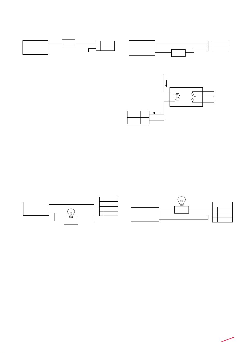
POWER WIRING DIAGRAM
Power Supply
12 - 24 VDC
12 - 24 VDC
+ VDC
- VDC
2
1
LOOP WIRING DIAGRAM

8
Internal PLC
connection
N.O.
COM
4
3
PLC
Imax = 50 mA
Power sup.
Power sup.
O.C. IN
O.C. IN
SOLID-STATE RELAY WIRING DIAGRAM
(FOR SSR1 AND SSR2)
INPUT WIRING DIAGRAM
Connection to a PLC with NPN input
Active loop devices Passive loop devices
Connection to a PLC with PNP input
N.O.
COM
4
3
PLC
Imax = 50 mA
Power sup.
Power sup.
O.C. IN
O.C. IN
Internal PLC
connection
Connection to a PLC / Instrument
digital input with separate Power
Supply
Connection to a PLC / Instrument
digital input for Voltage Free Contacts
(REED)
N.O.
COM
3
4
Power Supply
12 - 24 VDC
12 - 24 VDC
PLC / Instrument
Digital INPUT
Digital INPUT
Imax = 50mA
lmax = 50mA
lmax = 50mA
PLC
DIGITAL INPUT N
DIGITAL INPUT 2
DIGITAL INPUT 1
REF PLC
N.O.
Imax = 50 mA
Imax
COM
3
4
lmax = 50mA
lmax = 50mA
USB PORT
A USB port (type B) is available on the M9.10 PCB. The USB connection
allows the updating of device software. To update the software you need: USB
cable (M9.KUSB), the interface software "FLS Calibration System” and the
new updating software for M9.10 which are both downloadable from www.
snet.it freely on product page.
9
SOLID-STATE RELAY WIRING DIAGRAM
(FOR SSR1 AND SSR2)
RELAY WIRING DIAGRAM
(FOR RELAY 1 & RELAY 2)
The alarm is OFF during normal
operation and goes ON according to
Relay settings
The alarm is ON during normal
operation and goes OFF according to
Relay settings
The alarm is o during normal
operation and goes ON according to
Relay setting.
If Imax > 50 mA use external Relay
Connection to an User
NO
10
11
12
RELAY 2
NC
COM
Alarm
AC or DC
Power NO
10
11
12
RELAY 2
NC
COM
Alarm
AC or DC
Power
N.O.3
4 COM
AC or DC
Power
User
Imax = 50mA
N.O.3
4 COM
AC or DC
Power User
Imax = 50mA
lmax = 50mA
N.O.3
4 COM
AC or DC
Power
User
Imax = 50mA
N.O.3
4 COM
AC or DC
Power User Imax = 50mA
lmax = 50mA
N.O.
N.O.
N.C.
COM
4
3
COM
External Relay
V= 12-24 VAC/VDC
Imax = 50 mA
Imax
Imax
+V
-V lmax = 50mA

10
OPERATIONAL
OVERVIEW
The M9.10 Dual Analog Input Monitor and Transmitter
features a full graphic display and a ve-button keypad
for system set-up, calibration and operation. Full graphic
display has a white backlight during standard conditions,
a red backlight in case a set alarm is activated (MAX,
MIN, WINDOW IN, WINDOW OUT MODE: always with
priority), a green backlight in case a external device
control is activated (PROPORTIONAL FREQUENCY,
PROPORTIONAL PULSE, TIMED MODE, ON-OFF MODE)
VIEW LEVEL
MENU DIRECTORY
↓
↓
IN1 - IN2
(Delta IN1-IN2)**
IN 2 – OUT mA 2
IN 1 – OUT mA 1
Output Settings ***
Settings
Calibration
Outputs
Options
View data
Adjust
input mA
* For negative values rstly set the corresponding positive value
and then move the position indicator beyond the last position on
the right using to get the minus sign (not available for ow measurement)
*** for more info about Outputs
**** Use the same Engineering Unit on both INPUTS
** Delta visualization can be activated in Options Menù.
1SSR , 3 RELAY, 4-20 mA 1 can be assigned to the rst input.
2 SSR, 4 RELAY, 4-20 mA 2 can be assigned to the second input.
SET THE
FOLLOWING
PARAMETERS
SET THE
FOLLOWING
PARAMETERS
FIRST INPUT:
CURRENT
SECOND INPUT:
CURRENT
INPUT UNIT INPUT UNIT
INPUT 4 mA* INPUT 4 mA*
INPUT 20 mA* INPUT 20 mA*
↓
↓
Tabla de contenidos
Otros manuales de Transmisor de FIP


Manuales populares de Transmisor de otras marcas


Dejero
Dejero EnGo 3x Manual de usuario

Rosemount
Rosemount 4600 Manual de usuario

Speaka Professional
Speaka Professional 2342740 Manual de usuario

trubomat
trubomat GAB 1000 Manual de usuario

Teledyne Analytical Instruments
Teledyne Analytical Instruments LXT-380 Manual de usuario

Rondish
Rondish UT-11 Manual de usuario


