Filtertechnik PC9001 Manual de usuario


Table of contents
Specifications on page 3
General information on page 4
Installation on page 6
User interface and navigation on page 11
Operation on page 12
Data management on page 14
Maintenance on page 17
Troubleshooting on page 18
Replacement parts and accessories on page 20
Specifications
Specifications are subject to change without notice.
Specification Details
Dimensions (L x W x H) 8.9 x 10.7 x 8.9 cm (3.5 x 4.2 x 3.5 in.)
Enclosure IP 66
Fitting connections SAE -4; SAE -8
Power requirements 9 to 33 VDC, 150 mA
Storage temperature –40 to 85 °C (–40 to 185 °F)
Operating temperature –10 to 60 °C (–14 to 140 °F)
Altitude limit 2000 m (6562 ft)
Overvoltage category I
Pollution degree 4
Protection class III
Light source Laser diode, Class I
Particle size/channel 4, 6, 14 and 21 μm (ISO MTD)
Storage/operating humidity 97% relative humidity, non-condensing
Fluid compatibility Hydraulic and lubrication oils, mineral, synthetic (phosphate ester compatible)
Fluid viscosity 2 to 424 cSt1
Reports ISO 4406, NAS and SAE cleanliness codes
Wetted materials Brass, aluminum (anodized), steel, stainless steel, sapphire, Aflas®
Performance verification Optional validation certificate available (ISO MTD at 2.8 mg/L concentration)
Reproducibility ±0.5 ISO code (minimum concentration ISO MTD 2.8 mg/L, maximum ISO code
is 29)
Weight 746 grams (2 lb)
Serial interface RS232 and RS485, 9600 Baud, 8 data bits, no parity, 1 stop bit
Communication protocol MODBUS RTU
Flow rate for 3&-31, 3&-61 50 to 500 mL/min (0.01 to 0.1 gal/min)
Flow rate for 3&-21, 3&-51 3.8 to 45.4 L/min (1 to 12 gal/min)
Sample pressure PC9001-71, PC9001-81: 12 to 100 psi
Sample temperature 0 to 60 °C (32 to 140 °F)
Sample pressure 20 to 7250 psi
English 3
Specification Details
Warranty 1 year
Certifications CE and FDA Accession No. 9320350-008
1Viscosities tested at ambient temperature: 25 °C ±2 degrees; 77 °F ±2 degrees
General information
In no event will the manufacturer be liable for direct, indirect, special, incidental or consequential
damages resulting from any defect or omission in this manual. The manufacturer reserves the right to
make changes in this manual and the products it describes at any time, without notice or obligation.
Revised editions are found on the manufacturer’s website.
Safety information
N O T I C E
The manufacturer is not responsible for any damages due to misapplication or misuse of this product including,
without limitation, direct, incidental and consequential damages, and disclaims such damages to the full extent
permitted under applicable law. The user is solely responsible to identify critical application risks and install
appropriate mechanisms to protect processes during a possible equipment malfunction.
Please read this entire manual before unpacking, setting up or operating this equipment. Pay
attention to all danger and caution statements. Failure to do so could result in serious injury to the
operator or damage to the equipment.
Make sure that the protection provided by this equipment is not impaired. Do not use or install this
equipment in any manner other than that specified in this manual.
Use of hazard information
D A N G E R
Indicates a potentially or imminently hazardous situation which, if not avoided, will result in death or serious injury.
WARNING
Indicates a potentially or imminently hazardous situation which, if not avoided, could result in death or serious
injury.
CAUTION
Indicates a potentially hazardous situation that may result in minor or moderate injury.
N O T I C E
Indicates a situation which, if not avoided, may cause damage to the instrument. Information that requires special
emphasis.
Precautionary labels
This is the safety alert symbol. Obey all safety messages that follow this symbol to avoid potential
injury. If on the instrument, refer to the instruction manual for operation or safety information.
This symbol indicates that a risk of electrical shock and/or electrocution exists.
4 English

This symbol indicates a laser device is used in the equipment.
Electrical equipment marked with this symbol may not be disposed of in European public disposal
systems after 12 August of 2005. In conformity with European local and national regulations (EU
Directive 2002/98/EC), European electrical equipment users must now return old or end-of-life
equipment to the Producer for disposal at no charge to the user.
Note: For return for recycling, please contact the equipment producer or supplier for instructions on how to return end-
of-life equipment, producer-supplied electrical accessories, and all auxiliary items for proper disposal.
Certification
Canadian Radio Interference-Causing Equipment Regulation, IECS-003, Class A:
Supporting test records reside with the manufacturer.
This Class A digital apparatus meets all requirements of the Canadian Interference-Causing
Equipment Regulations.
Cet appareil numèrique de la classe A respecte toutes les exigences du Rëglement sur le matériel
brouilleur du Canada.
FCC Part 15, Class "A" Limits
Supporting test records reside with the manufacturer. The device complies with Part 15 of the FCC
Rules. Operation is subject to the following conditions:
1. The equipment may not cause harmful interference.
2. The equipment must accept any interference received, including interference that may cause
undesired operation.
Changes or modifications to this equipment not expressly approved by the party responsible for
compliance could void the user's authority to operate the equipment. This equipment has been tested
and found to comply with the limits for a Class A digital device, pursuant to Part 15 of the FCC rules.
These limits are designed to provide reasonable protection against harmful interference when the
equipment is operated in a commercial environment. This equipment generates, uses and can
radiate radio frequency energy and, if not installed and used in accordance with the instruction
manual, may cause harmful interference to radio communications. Operation of this equipment in a
residential area is likely to cause harmful interference, in which case the user will be required to
correct the interference at their expense. The following techniques can be used to reduce
interference problems:
1. Disconnect the equipment from its power source to verify that it is or is not the source of the
interference.
2. If the equipment is connected to the same outlet as the device experiencing interference, connect
the equipment to a different outlet.
3. Move the equipment away from the device receiving the interference.
4. Reposition the receiving antenna for the device receiving the interference.
5. Try combinations of the above.
Class 1 laser product
This instrument is classified as a Class 1 laser product. This product complies with IEC/EN
60825-1:2007 and 21 CFR 1040.10 except for deviations pursuant to Laser Notice No. 50, dated
June 24, 2007.
US FDA Laser Accession number 9320350-008. This product contains a 780 nm 5 mW class 3B
laser that is not user-serviceable.
Product overview
This instrument is used to validate the cleanliness level and particulate count in oil. The data can be
viewed on the instrument display or a computer. The software shows the current data or previously
English 5

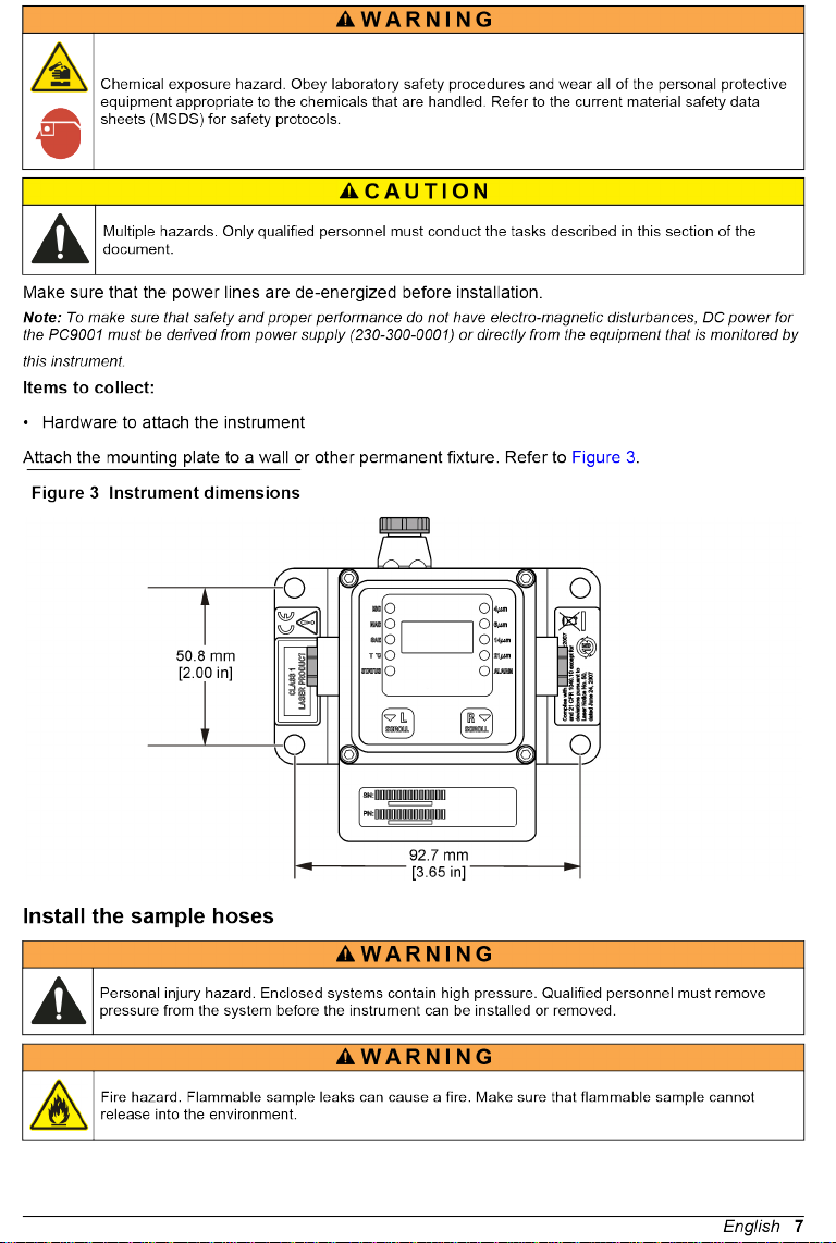


Figure 5 Cable connections
1 9 to 33 VDC 2 Alarm driver
Table 1 Male connector wires—DB15 cable
Pin number Color Function
1 White Power input (9 to 33 VDC)
2 Brown Power ground (return)
3 Green Alarm driver
4 Yellow —
5 Gray RS232-RXD (receive data)
6 Pink RS232-TXD (transmit data)
7 Blue —
8 Red —
9 Orange RS232-GND (signal return)
10 Tan RS485-A (signal A of differential serial driver pair)
11 Black RS485-B (signal B of differential serial driver pair)
12 Violet RS485-SGND (shield ground connection)
Table 2 Female connector wires—DB15 cable
Pin number Color Function
1 White Power input (9 to 33 VDC)
2 Brown Power ground (return)
3 Green Alarm driver
4 Yellow —
5 Gray RS232-RXD (receive data)
English 9
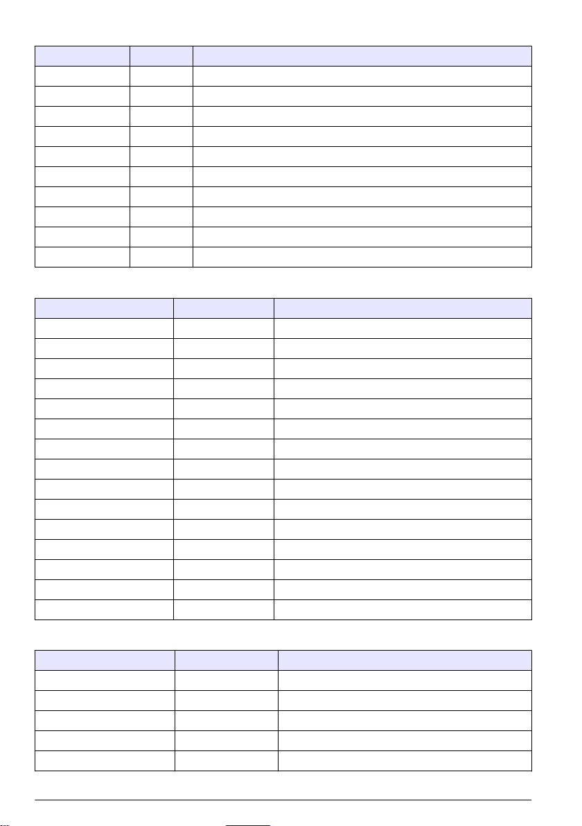
Table 2 Female connector wires—DB15 cable (continued)
Pin number Color Function
6 Pink RS232-TXD (transmit data)
7 Blue —
8 Red —
9 Orange RS232-GND (signal return)
10 Tan RS485-A (signal A of differential serial driver pair)
11 Black RS485-B (signal B of differential serial driver pair)
12 Violet RS485-SGND (shield ground connection)
13 — —
14 — —
15 — —
Table 3 Male connector wires—DB15 to DB9 cable
Pin number Color Function
1 Red1 Power input (9 to 33 VDC)
2 Black1 Power ground (return)
3 White1 Alarm driver
4 — —
5 Red2 RS232-RXD (receive data)
6 Black2 RS232-TXD (transmit data)
7 — —
8 — —
9 White2 RS232-GND (signal return)
10 — —
11 — —
12 — —
13 — —
14 — —
15 — —
Table 4 Female connector wires—DB15 to DB9 cable
Pin number Color Function
1 — —
2 Black2 RS232-TXD (transmit data)
3 Red2 RS232-RXD (receive data)
4 — —
5 White2 RS232-GND (signal return)
10 English

Este manual sirve para los siguientes modelos
6
Tabla de contenidos


