P/N06‐791‐2(Rev.1)Page7
704SW10thStreet,P.O.Box610,BlueSprings,Missouri64013‐0610U.S.A.●Phone:(816)229‐3405●www.fike.com
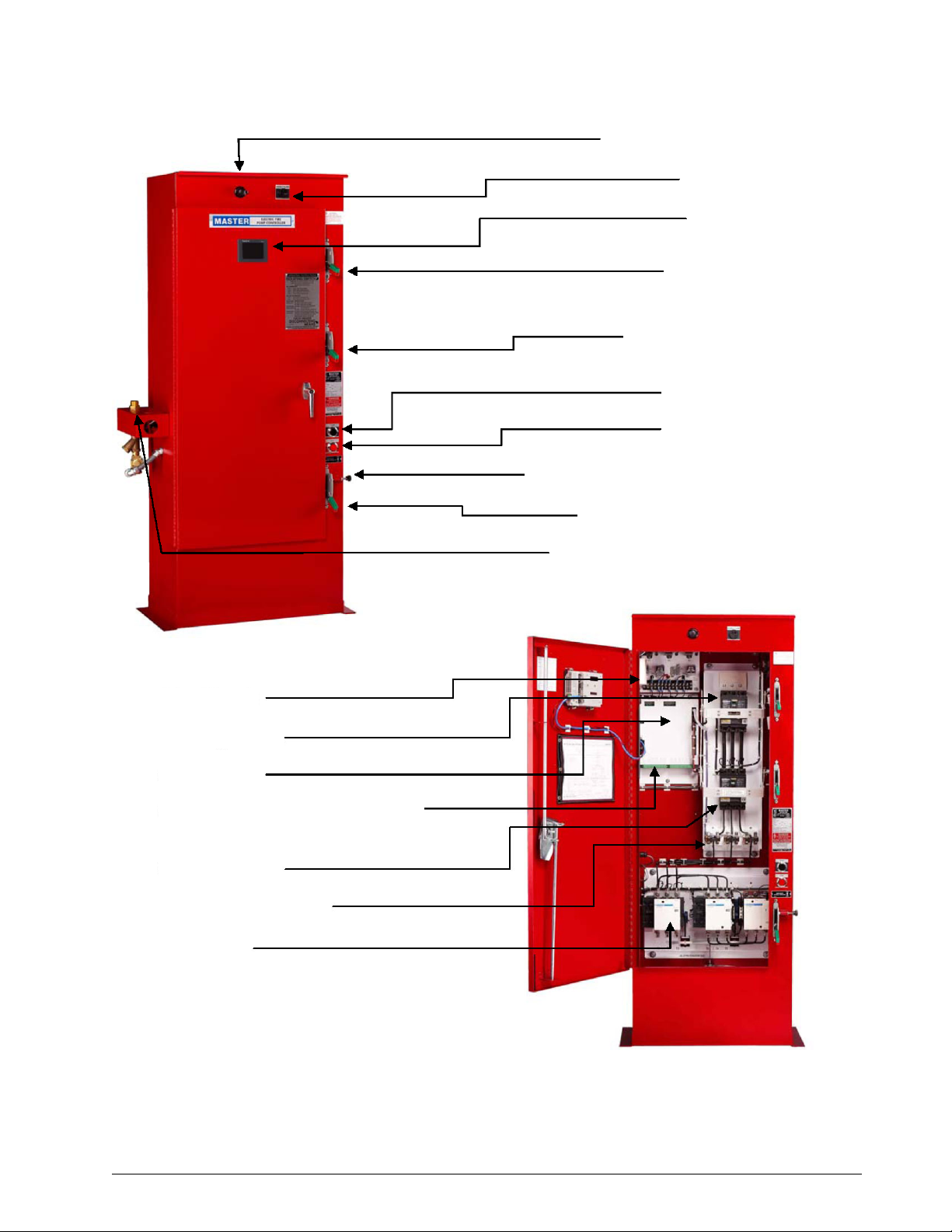
2.3. MOTORCIRCUITCONDUCTORS
ThepumpmotorontheDuraQuenchpumpskidispre‐wiredtothecontrollerpriortoshipmentfromthefactory.Circuit
conductorsaresecuredinsuchamannersotheywillnotmoveorinterfereorrubagainstanycomponentsor
mechanismswithsharpedgesorcornersthataremountedonthepumpskidorcontainedwithinthecontrollercabinet.
Theoutputmotorwiringisconnectedtothebottomofthecontroller’sMainContactorMloadsideterminallugsT1,
T2,andT3.RefertotheExternalWiringdiagramlocatedneartheendofthismanualfordetails.
AllmotorcircuitconductorsaresizedaccordingtotheNationalElectricCode(NFPA‐70)onacontinuousdutybasis.
Insulationfortheseconductorsischosensoitwillnotbeaffectedbythesurroundingenvironmentandwillhavean
insulationtemperatureratingatleast90degreesCforanambientof40Coratleast105Cforanambientof50C.
Theampacityofthewireisbasedon125%ofthemotorfullloadcurrent(FLA)usingthe60Ccolumnfor100ampsor
lessandthe75Ccolumninfieldwiringtable310.15(B)(16)ofthe2011editionoftheNFPA70forhighercurrents.Also,
applyingtheappropriatecorrectionfactorsinaccordancewith310.15(B)(1)through310.15(B)(7).
NOTEThecontrollerisServiceEntranceRatedsoadualgroundinglugisprovidedforthegroundingelectrode
conductorandthegroundedserviceconductor.Noneutralconnectionisprovidedorneeded.Thecontroller
issuitableforuseoneitherthreewireorfourwiresystemswithouttheuseofaneutral.
NOTEThecontrollerisnotdesignedtobeusedasajunctionboxforanypurpose,includingthefollowing:(1)tosupply
otherequipment,(2)tospliceincomingoroutgoingwires,or(3)toconnectexternalsurgesuppression.
WARNINGAfaultymotororfaultywiringcancauseelectricshockthatcouldbefatal,whetherthemotoristouched
directlyorthecurrentisconductedthroughstandingwater.Forthisreason,safeinstallationandoperation
requirepropergroundingofthepumptothepowersupplyground(earth)terminal.
Inallinstallations,connecttheabove‐groundmetalplumbingtothepowersupplygroundterminalasdescribedin
Article250‐80ofNFPA70,NationalElectricalCode.
Verifythepowersupplytomakesurethatthevoltage,phasesandfrequencymatchthoseofthepump.Theproper
operatingvoltageandotherelectricalinformationappearonthemotornameplate.Themotorisdesignedtorunon‐
10%/+10%oftheratednameplatevoltage.Fordual‐voltagemotors,themotorshouldbeinternallyconnectedto
operateonthevoltageclosesttothe10%rating,i.e.,a208Vmotorshouldbewiredaccordingtothe208Vwiring
diagram.Thewiringdiagramcanbefoundoneitheraplateattachedtothemotororonalabelinsidetheterminalbox
cover.
CAUTIONDonotoperatethepumpifvoltagevariationsaregreaterthan‐10%/+10%.
2.4. REMOTEALARMCONNECTIONS
Thepumpcontrollerprovidesthefollowingrelayconnectionsforpumpsupervision.Thecontactsshallbemonitoredby
thereleasingcontrolpanelinaccordancewithNFPA750,StandardonWaterMistFireProtectionSystems.Seewiring
diagramsneartheendofthismanualforcontactratinglimitations.
1. PumpRunningSignal‐Terminalsnumbered5,6,and7provideaform"C"setofcontactswhichtransferwhenthe
motorcurrentisdetected.Contactsonterminals5and6closeinthealarmstate,whilecontactsonterminals6and
7openinthealarmstate.
2. PumpRunningSignal(2ndset)‐Terminalsnumbered8,9,and10provideaform"C"setofcontactswhichtransfer
whenthemotorcurrentisdetected.Contactsonterminals8and9closeinthealarmstate,whilecontactson
terminals9and10openinthealarmstate.