LIT 9003
©2012 EXAIR Corporation
Timer
WARNING – To prevent shock hazard, all adjustments to the EFC
timer control must be made with the unit unplugged. Following
adjustment, the cover must be installed before restoring power.
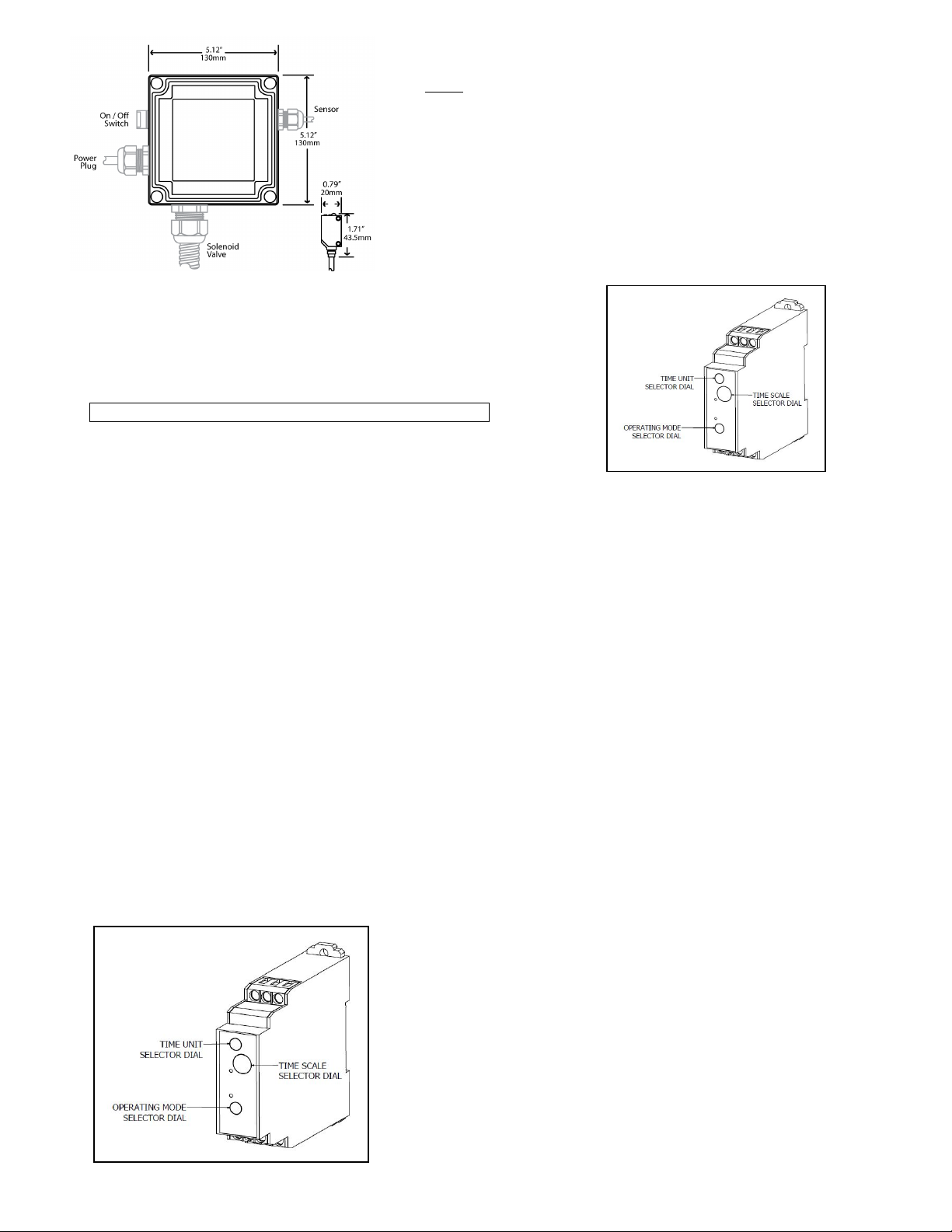
There is a timer Main Dial, Time Range selector, Time Unit selector and
Operating Mode Selector. The selectors can be turned clockwise and
counterclockwise (using a Phillips screwdriver) to select the desired time
unit, time scale, or operating mode. Each selector has a snap mechanism
that secures the selector at a given position. Set each selector at a
position at which it is secured. Do not set it midway between two
securing positions or a malfunction could result from improper setting.
1. Determine the Operating Mode that suits your application.
The operating mode selector can be set to any one of the
eight operating modes “A” to “J”. Turn the operating mode
selector (bottom dial) with a screwdriver until the arrow is pointing
to the desired mode.
NOTE: The EFC factory setting is “Signal OFF Delay” (D).
The following describes all of the available modes:
A: “ON” Delay ………...…………........The sensor will detect the part, delay opening the solenoid valve per the timer setting and
operate continuously until the power to the EFC is turned off.
B: Flicker “OFF” Start ….…............…The sensor will detect the part, delay opening the solenoid valve per the timer setting,
close the solenoid valve per the timer setting, open per the setting, close per the setting – a continuous operation
(cycle continues after the part is gone).
C: Signal On w/“Off Delay”……….….The sensor will detect the part, open the solenoid valve immediately and begin the off
delay per the timer setting once the part has cleared the sensor beam. If the part remains in the sensor beam longer
than the timer setting, the valve will close until the part is no longer in the beam, at which point the valve will open
immediately, then close per the timer setting.
B2: Flicker “ON” Start …………...…..The sensor will detect the part, open the solenoid valve immediately per the timer setting,
close per the timer setting, open per the setting, close per the timer setting – a continuous operation (cycle continues
after the part is gone).
D: Signal “OFF” delay (Factory setting)..The sensor will detect the part, open the solenoid valve immediately. It will begin the
off delay per the timer setting once the part has cleared the sensor.
E: Interval ……………………….…….The sensor will detect the part, open the solenoid immediately and begin the interval
timer setting and close the valve per the interval setting, even if the part remains in the sensor beam. If the sensor
detects multiple parts within the interval setting, the timer will restart the timing interval when it senses an object
staying in front of the sensor or when the part has cleared with no other part moving into position.
J: One-Shot …………….………………The sensor will detect the part, delay opening the solenoid valve per the timer setting,
open the valve for one second, close the solenoid valve and repeat at the next detection.
G: Signal “On Delay/Off Delay” ……..The sensor will detect the part, then start the “ON” delay time interval of the timer
setting. The solenoid valve will open when the time setting is reached, regardless if the part is still present in front of
the sensor or not. The “OFF” delay will begin only when the part has cleared the sensor. The solenoid valve will
close when the time setting is reached, per the timer setting. The time setting delay is the same for “ON” and “OFF”.
2. Selection of time unit and time scale
a. On the top dial of the module, select the desired time unit(0.1 s, 1s,
10s, 1m, 10m, 1h, 10h or 100h). Turn the time selector with a
screwdriver until the arrow is pointing at the desired time unit.
b. On the middle dial of the module, select the time scale (1 to 12). Turn
the time scale selector with a screwdriver until the arrow is pointing at
the desired time.