EVA eva-36-CR Manual de usuario

www.evaelektromekanik.com
CABLE CONNECTION CUBICLE
36kV
METAL ENCLOSED MODULAR SWITCHGEARS
(MMMH) USER GUIDE
Assembly, Operating and Maintenance Instructions

EVA ELEKTROMEKANİK SAN. VE TİC. LTD. ŞTİ.
DAĞYAKA MAH. 2008. CAD. NO:5 KAHRAMANKAZAN, ANKARA, TÜRKİYE
Tel: +90 312 811 27 27 Fax: +90 312 811 27 28
www.evaelektromekanik.com
All rights reserved. Any part of this catalogue can not be copied without the permission of the right holder. It can only be copied
and augmented with the written permission of EVA ELEKTROMEKANİK SAN. VE TİC. LTD. ŞTİ.
Switching The Future...

CONTENTS
1. GENERAL FEATURES 2
1.1 GENERAL SECTIONS 2
1.2 STANDARDS 2
1.3 CHARACTERISTIC FEATURES 3
2-LOADING - UNLOADING - TRANSPORTING 4
2.1 TRANSPORTING WITH FORKLIFT 4
2.2 TRANSPORTING OVER THE PIPE 4
2.3 TRANSPORTING BY LIFTING SLING 5
3 - INSTALLATION 5
3.1 - TOOLS LIST REQUIRED DURING INSTALLATION 5
3.2 - MATERIALS LIST SENT WITH THE CUBICLE 5
3.3 - CUBICLE’S PLACEMENT 6
3.4 - CONNECTING THE CUBICLES TO EACH OTHER 7
3.5 -MAIN BUSBARS CONNECTION 8
3.6 – EARTHING BUSBARS CONNECTION 9
3.7 - CONNECTING THE CUBICLES’ ARRAY TO THE MAIN GROUNDING SYSTEM OF THE FACILITY 9
3.8 –PASSAGES OF AUXILIARY SERVICE AND CONTROL CABLES FROM CUBICLE TO ANOTHER 10
3.9 - CONNECTION OF MV CABLES 11
3.10 - MATTERS TO BE CONSIDERED AGAINST INTERNAL ARC WHEN THE CUBICLE IS MOUNTED 11
4 - COMMISSIONING 12
4.1 - CHECKS TO BE PERFORMED BY THE BARE EYE 12
4.2 - MECHANICAL CHECKS 12
4.3 - SUPPLYING VOLTAGE TO THE MAIN BUSBAR AND REQUIRED CHECKS 12
4.4- OPERATING THE CABLE CONNECTION CUBICLE 12
4.5- SHUTTING DOWN THE CABLE CONNECTION CUBICLE 12
5 - MAINTENANCE INSTRUCTIONS AND RECOMMENDATIONS FOR THE AIR
INSULATED METAL ENCLOSED CUBICLES MMMH TYPE 13
5.1-MAIN BUSBAR COMPARTMENT 13
5.2 LIST OF TOOLS REQUIRED DURING MAINTENANCE AND INSTALLATION 13
6 - GUARANTEE TERMS 13

www.evaelektromekanik.com
2
1- GENERAL FEATURES
eva-36-CR is an sf6 gas insulated switchgear used for medium voltage distribution networks. eva-36-CR, and as
desired, can be supplied in a combined form. By performing all the required tests and the related quality control
processes to all the modulars, the products will be ready for delivery and installation.
1.1 GENERAL SECTIONS
eva-36-CR SWITCHING SYSTEM IS FULLY COMPLIANT WITH TS EN / IEC 62271-1, TS EN / IEC 62271-200 STAN-
DARDS. ALSO, THIS SWITCHING SYSTEM HAS A PROTECTION CLASS OF IP3X ACCORDING TO TS EN / IEC 60529
STANDARDS.
TO INSTALL, OPERATE AND MAINTAIN THIS EQUIPMENT SAFELY, TSE AND IEC REGULATIONS MUST BE FOL-
LOWED.
1.2 STANDARDS

www.evaelektromekanik.com 3
Rated Voltage (kV) 36
Type eva-36-CR
Main Busbar Rated Current (A) 630 – 1250
Feeder Rated Current 630 – 1250
Rated power frequency withstand voltage
(KV rms)
70
Rated Lightning Impulse Withstand Voltage (kV) 170
Rated Short Circuit Withstand Current (rms) 16kA / 1sec
Rated Peak Withstand Current (kA-Peak) 40
Loss of Service Continuity Class LSC 2A – PI *
Internal Arc Classication (Cable Connection
and Main Busbar)
IAC – A(FL) 16kA / 1sec
Protection Level (TS 3033 EN 60529) IP3X
Applied Standard TS EN / IEC 62271-1, TS EN / IEC 62271-200
Height (mm) 2250
Width (mm) 750
Depth (mm) 1400
1.3 KARAKTERİSTİK ÖZELLİKLER
* LSC 2A - PI DESCRIPTION
LSC 2A Loss of Service Continuity
2A When Interfering to the Accessible Part of a Cubicle like the Cable Connection Compartment and
de-energizing it, Neighboring Cubicles May Be Still Energized. In other words, Service Continuity is
Not Restricted.
PI P: There Are Multiple Sections.
I: These Sections Are Separated From Each Other By Insulating Material.

www.evaelektromekanik.com
4
2- LOADING - UNLOADING - TRANSPORTING
Loading, unloading and transporting methods of the MMMH type cubicles are shown below:
Cubicles can be carried either way as shown in the the pictures below. In addition, forklift is usually
used to unload the cubicles from the truck and transport them to the assembly site.
2.1 TRANSPORTATING WITH FORKLIFT
Pipe Transporting is used to line up and dock the cubicles. Never use Cranks while transporting the cubicles.
2.2 TRANSPORTING OVER THE PIPE

www.evaelektromekanik.com 5
Cubicles can be transported with
the help of sling lifting by means
of a crane. Usually it is used while
unloading the cubicles from the
truck.
2.3 TRANSPORTING BY
LIFTING SLING
3 - INSTALLATION
3.1 - TOOLS LIST REQUIRED DURING INSTALLATION
3.2 - MATERIALS LIST SENT WITH THE CUBICLE
Tools Dimensions Quantity
Open End Wrench 10’’ 2 Pcs
Open End Wrench 13’’ 2 Pcs
Open End Wrench 15’’ 1 Pcs
Open End Wrench 17’’ 1 Pcs
Open End Wrench 19’’ 1 Pcs
Open End Wrench 24’’ 1 Pcs
Torque Wrench -1 Pcs
Socket Wrench -1 Pcs
Socket 10’’, 13’’, 15’’, 17’’, 19’’, 24’’ 1 Pcs
Plumb bob -1 Pcs
Crank -1 Pcs
Materials Quantity
M8x20 Flange bolt 15 Pcs
M8 Nut 15 Pcs
Operating Lever 1 Pcs
Main Busbar 3 Pcs
Earthing Busbar 1 Pcs
Remote control 1 Pcs
www.evaelektromekanik.com
6
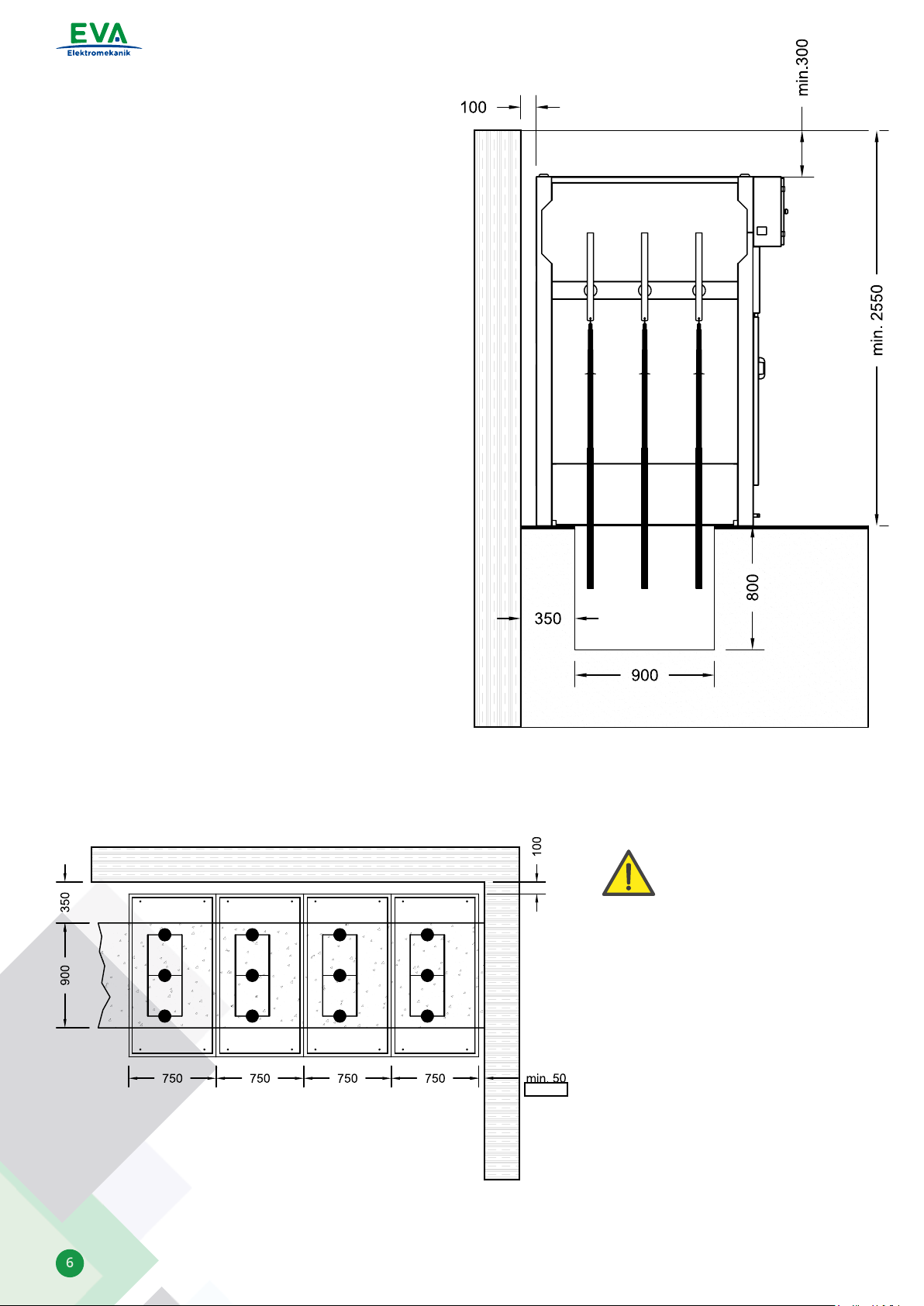
• Place the MMMH Type cubicle on a channel inside
the building in accordance with the dimensions
indicated in the right picture.
•
• A 5cm gap should be left between the placed
cubicles on the right or the left side inside the
building and the wall.
•
• Close the channel gaps.
•
• Do not go below the dimensions indicated in the
right picture.
3.3.1 Placement inside the Building:
3.3 - CUBICLE’S PLACEMENT
• Base holes that enable the cubicles to be xed to the ground are provided as shown in the below picture.
• Fix the cubicles to the ground by using M10 steel peg or iron dowel.
• The dispatched cubicles should
be placed on the side and
according to the illustrated
gure.
• Do not go below the provided
dimensions.
• The building dimensions can be
determined accordingly.
• The gaps between the cubicles
from one side and the ceiling
and the back wall from the other
side should be at least 300mm
and 100mm respectively.
IMPORTANT WARNING:

www.evaelektromekanik.com 7
3.4 - CONNECTING THE CUBICLES TO EACH OTHER
The lower holes dimensions are provided in the picture below. Based on these dimensions a steel peg or an iron
dowel should be used. Then the holes to be xed with M10x50 bolts.
MV Cable Entry Point
Pull the lifting hooks upwards (See below pictures). Bring the cubicles to the settlement area by using the relevant
transport apparatus and taking into consideration the “Loading - Unloading Transporting” instructions.
THE BASE METAL HOLE DIMENSIONS OF THE CUBICLE
www.evaelektromekanik.com
8
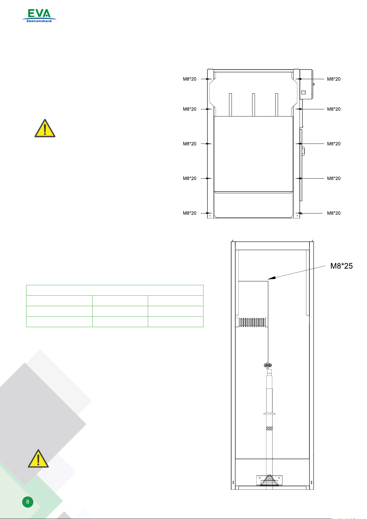
In accordance with the single line diagram of the facility, combine the square-shaped holes of the cubicles side by
side using M8x20 bolts.
1. According to the “3.3- CUBICLE’S PLACEMENT” article stated
above, remove the upper cover plate of the connected
cubicles.
2. Connect the main busbars shipped with the cubicles to the
main bus terminal using eld regulators and tighten the bolts
with 50Nm torque.
3. Wipe the insulators and solid insulation materials with a dry
clean cloth.
4. Assemble the upper cover plate.
IMPORTANT WARNING: If the surface
on which the cubicles will be mounted
is not at, the cubicles’ covers may not
be tted properly and also problems
may be caused in the main busbar
connection.
3.5 -MAIN BUSBARS CONNECTION
MAIN BUSBAR TYPES:
MAIN BUSBAR CURRENT AND THICKNESS
Busbar Material 630 A 1250 A
Copper (Cu) 40x5 mm260x10 mm2
Aluminum (Al) 40x10 mm2*
IMPORTANT WARNING: Do not step or walk on the
main busbars, disconnectors and load break switches.
Tabla de contenidos
Otros manuales de Cambiar de EVA


