EV Hub Hypervolt Home 2.0 Manual de usuario

Page 1 of 24
www.ev-hub.com.au
Hypervolt Home 2.0
Installation Manual
Nov 2021

Page 2 of 24
www.ev-hub.com.au
Contents
Hypervolt Home 2.0 – Installation Guide ........................................................................................................... 4
1 – Positioning the Hypervolt Home .................................................................................................................. 4
2 – Preparing the Hypervolt Unit ....................................................................................................................... 4
3 – Securing the Hypervolt on the wall .............................................................................................................. 5
4 – Electrical Wiring ............................................................................................................................................ 6
5 – Finishing Off .................................................................................................................................................. 7
Hypervolt ALM V1.0 – Setup Guide .................................................................................................................... 9
1. Introduction ............................................................................................................................................ 9
2. How it works ........................................................................................................................................... 9
3. Wiring and setting up ............................................................................................................................. 9
Hypervolt Home 2.0 – Getting Started ............................................................................................................. 12
1 Your new Hypervolt Home 2.0 .................................................................................................................. 12
2 Get your Hypervolt online ......................................................................................................................... 12
2.1 Connecting the Hypervolt to the Wi-Fi network ............................................................................... 12
2.1.1 Step 1 ......................................................................................................................................... 13
2.1.2 Step 2 ......................................................................................................................................... 14
2.1.3 Step 3 ......................................................................................................................................... 15
2.1.4 Step 4 ......................................................................................................................................... 16
2.1.5 Step 5 ......................................................................................................................................... 16
Sign up for the Hypervolt Dashboard ............................................................................................................... 17
3 Registering your Hypervolt Home and using the dashboard .................................................................... 17
3.1 Before you start, you will need: ........................................................................................................ 17
3.1.1 Step 1 ......................................................................................................................................... 18
3.1.2 Step 2 ......................................................................................................................................... 18
3.1.3 Step 3 ......................................................................................................................................... 19
3.1.4 Step 4 ......................................................................................................................................... 19
3.1.5 Step 5 ......................................................................................................................................... 20
3.1.6 Step 6 ......................................................................................................................................... 20
Get familiar with the different colours ............................................................................................................ 21
1. Setup mode: Blue Bolt & White Ring. .................................................................................................. 21
2. Stand-by: Blue. ...................................................................................................................................... 21
3. Charging in progress: Green. ................................................................................................................ 22

Page 3 of 24
www.ev-hub.com.au
4. Charging curtailed on schedule: Purple. ...........................................22
5. The unit is locked: Orange .................................................................................................................... 22
6. An error has occurred: Red. .................................................................................................................. 23
Disclaimer .......................................................................................................................................................... 24
Page 4 of 24
www.ev-hub.com.au
Hypervolt Home 2.0 – Installation Guide
1 – Positioning the Hypervolt Home
We advise that this should be the first action to be completed on-site. The installer should consult the
customer and establish their preferred installation location. This should take into consideration the cable
length (distance to the vehicle being charged), risk of vehicle impact and obstruction of access.
Keep in mind that the customer may change their mind with regards to the charger location once into place
and it is desirable this happens prior to routing any of the cables.
The Hypervolt Home 2.0 can be fitted indoors or outdoors.
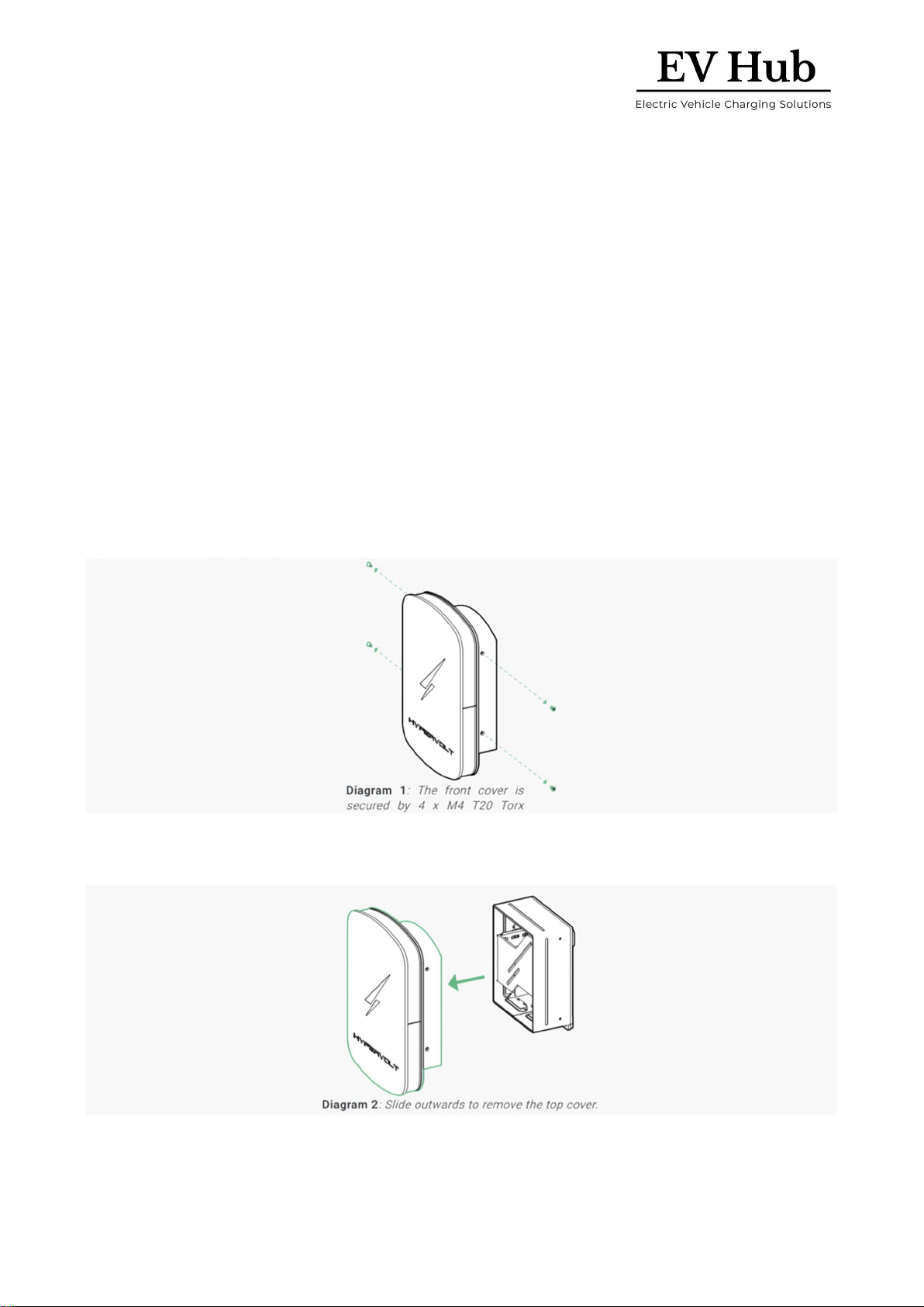
2 – Preparing the Hypervolt Unit
In order to install the Hypervolt unit, you will need access to the main wiring terminal inside the device.
Place the unit on a secure surface and using a T20 Security Torx screwdriver, remove the 4 off screws (2 on
each side) which secure the front cover in place.
Remove the top cover. Simply slide it away from the rest of the unit. There should be almost no resistance in
doing so.

Page 5 of 24
www.ev-hub.com.au
Place the top cover and its screws somewhere safe.
Next, carefully disconnect the connector at the back of the LED panel, pop out the LED assembly from its
side slots and place it somewhere safe.
3 – Securing the Hypervolt on the wall
Using the drilling template and integrated spirit level provided in your kit, drill the holes to an appropriate
length and diameter suitable for the fixing you are going to use.
Screw in the top 2 mounting screws into their holes. Leave approximately 7-8mm from the surface of the
wall. Refer to Diagram 5.

Page 6 of 24
www.ev-hub.com.au
Next, position the Hypervolt and hang it onto the 2 mounting points.
Double-check that the bottom 2 mounting holes are well aligned and insert the last 2 screws. The unit should
now be safely in place.
You do not need to fit the top cover back on yet, as you will need access to the wiring terminals later on.
However, you may wish to place the cover on for protecting the insides of the charger from dust and other
debris during the rest of the installation.
At this stage, confirm with the customer they are happy with the location and height of the unit. Make sure
you do this prior to routing any cables as customers may change their mind!
4 – Electrical Wiring
The next step is to complete the electrical connections between the distribution panel and the Hypervolt
Home device. Diagram 8 is provided as a reference for a typical installation diagram for the charging station.
The installation should be done in accordance with the applicable local electrical regulations.
Page 7 of 24
www.ev-hub.com.au
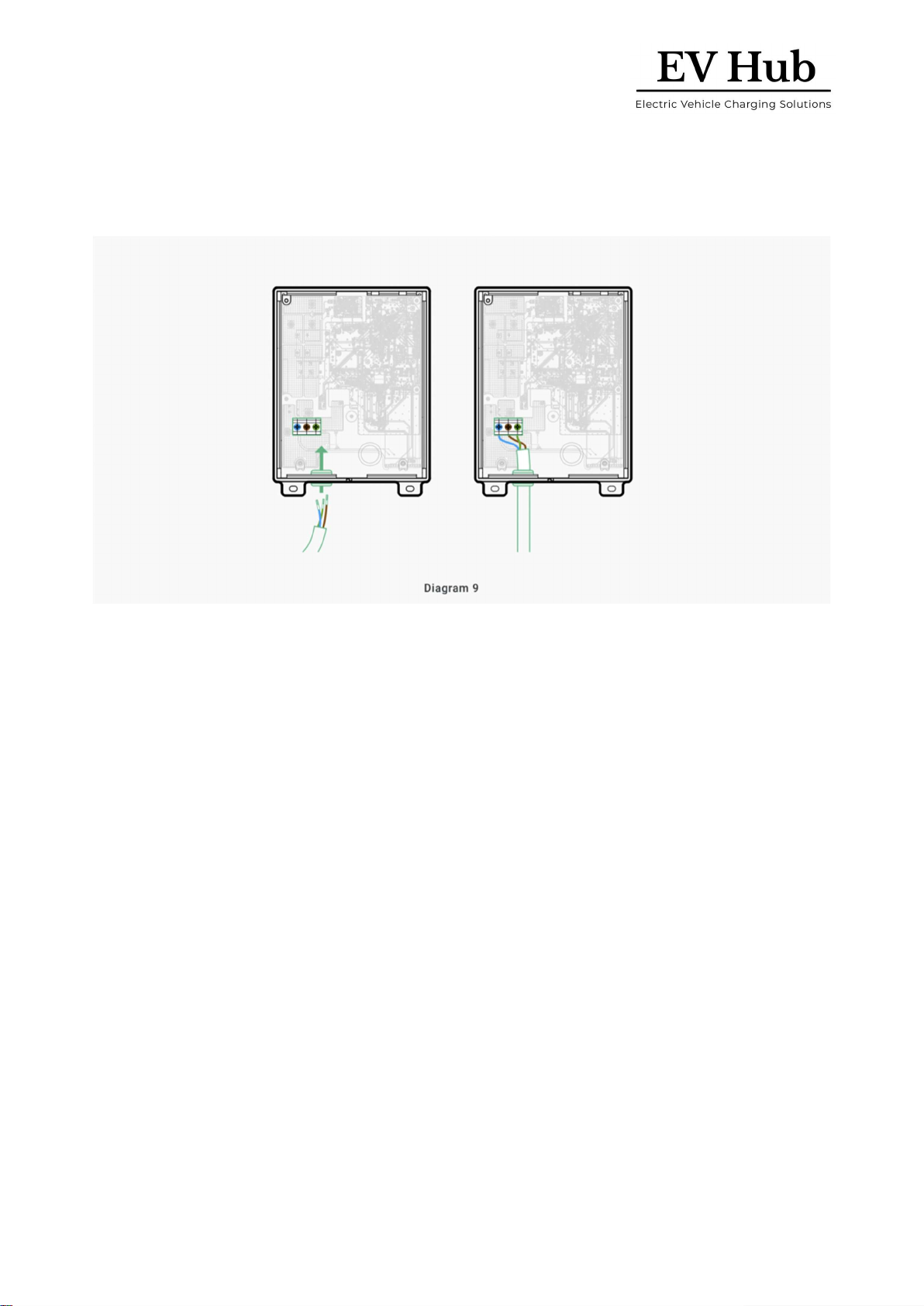
Next, proceed to make the electrical connections inside the Hypervolt
device. Refer to Diagram 9 to identify the cable entry location and the power input connector inside the unit.
All of the cables that are to be connected into the supply terminals should have their insulation stripped
back 12-15mm and have suitable ferrules crimped over in order to ensure the best electrical connection
possible.
Make sure you perform an adequate pull test at the unit electrical terminal to confirm the connection is
acceptable. The Hypervolt Home 2.0 incorporates an automatic thermal-based detection mechanism for
poor power input connections.
You should perform all required electrical tests at this stage.
5 – Finishing Off
Insert the LED panel back into its location. Ensure it clicks properly into place and it is not miss-aligned.
Lastly, place the top cover back onto the unit and secure using the 4 off screws. Take care to avoid cross-
threading during this process, as the water-tightness of the unit and its seals rely on these 4 screws being
into place.

Page 8 of 24
www.ev-hub.com.au
Updated on 3 July 2021

Page 9 of 24
www.ev-hub.com.au
Hypervolt ALM V1.0 – Setup Guide
1. Introduction
The Hypervolt ALM has been designed with ease of installation in mind. Its lightning-fast reaction time to
overload currents coupled with the fact that Hypervolt records the power and energy from the CT means
you will improve on the safety of your installation while gaining insights into the energy usage of the
property.
2. How it works
The Hypervolt works using a wired CT sensor which the installer must clip over the main incoming power
feed into the property. The Hypervolt CT is bidirectional meaning that the Hypervolt is able to differentiate
between export and import powers respectively.
Your property will have a maximum allowed total power consumption that can be configured inside your
Hypervolt. Once installed and configured, the charger monitors this consumption in real-time. In the event
that charging would cause you to exceed the pre-set limit, we will then reduce the EV charging rate in order
to protect your electrical wiring and avoid blowing the fuse in your meter whilst continuing to charge your
vehicle.
3. Wiring and setting up
CAUTION: make sure the Hypervolt is switched off and isolated from the mains before proceeding.
Connect the CT to the internal 2-pole signal connector provided inside the Hypervolt.
You must ensure the polarity of the CT is correct. The CT should be wired with the white lead into the left-
hand side terminal of the connector. The arrow on the CT should point in the direction of the load.
If you need to put the CT on the Neutral instead of the Live, the arrow on the CT should now
point opposite the load.

Page 10 of 24
www.ev-hub.com.au
Locate the rotary switch. It is situated adjacent to the CT connector you have plugged the CT into.
Use the following table to select the switch position which matches your requirements for the installation.
Note: Each installation is different; hence the settings will differ from site to site.
CT installed
ALM enabled
Fuse rating/max incomer load
Switch setting
No
No
n/a
0
Yes
No
n/a ***
1
Yes
Yes
10A
2
Yes
Yes
16A
3
Yes
Yes
32A
4
Yes
Yes
40A
5
Yes
Yes
60A
6
Yes
Yes
80A
7
Yes
Yes
100A
8
Yes
Yes
120A
9
Tabla de contenidos
Otros manuales de Cargador de baterías de EV Hub


