Eureka Microphone Preamplifier Manual de usuario

EUREKA
MICROPHONE PREAMPLIFIER
COMPRESSOR
PARAMETRIC EQUALIZER
USER’S MANUAL
version 3.0
©2003-2007, PreSonus Audio Electronics, Incorporated.
All rights reserved.

WARRANTY
PreSonus Limited Warranty
PreSonus Audio Electronics Inc. warrants this product to be free of defects in material
and workmanship for a period of one year from the date of original retail purchase.
This warranty is enforceable only by the original retail purchaser. To be protected by
this warranty, the purchaser must complete and return the enclosed warranty card
within 14 days of purchase. During the warranty period PreSonus shall, at its sole
and absolute option, either repair or replace, free of charge, any product that proves
to be defective on inspection by PreSonus or its authorized service representative.
To obtain warranty service, the purchaser must first call or write PreSonus at the
address and telephone number printed below to obtain a Return Authorization
Number and instructions of where to return the unit for service. All inquiries must be
accompanied by a description of the problem. All authorized returns must be sent to
the PreSonus repair facility postage prepaid, insured and properly packaged.
PreSonus reserves the right to update any unit returned for repair. PreSonus
reserves the right to change or improve the design of the product at any time without
prior notice. This warranty does not cover claims for damage due to abuse, neglect,
alteration or attempted repair by unauthorized personnel, and is limited to failures
arising during normal use that are due to defects in material or workmanship in the
product. Any implied warranties, including implied warranties of merchantability and
fitness for a particular purpose, are limited in duration to the length of this limited
warranty. Some states do not allow limitations on how long an implied warranty lasts,
so the above limitation may not apply to you. In no event will PreSonus be liable for
incidental, consequential or other damages resulting from the breach of any express
or implied warranty, including, among other things, damage to property, damage
based on inconvenience or on loss of use of the product, and, to the extent permitted
by law, damages for personal injury. Some states do not allow the exclusion of
limitation of incidental or consequential damages, so the above limitation or exclusion
may not apply to you. This warranty gives you specific legal rights, and you may also
have other rights, which vary form state to state. This warranty only applies to
products sold and used in the United States of America. For warranty information in
all other countries please refer to your local distributor.
PreSonus Audio Electronics, Inc.
7257 Florida Blvd.
Baton Rouge, LA 70806
(225) 216-7887
(800) 750-0323
www.presonus.com
©2003, PreSonus Audio Electronics, Incorporated. All rights reserved.

TABLE OF CONTENTS
3
1 Overview
1.1 Introduction 4
1.2 Features 4
2 Controls & Connections
2.1 Front Panel Basic Layout 7
2.2 Preamplifier 9
2.3 Compressor 10
2.4 Equalizer 12
2.5 Master 13
2.6 Back Panel 13
2.7 Power Supply 14
3 Operation
3.1 Microphones 15
3.2 Send and Return 15
3.3 192k/24-Bit Digital Output Card 16
3.4 Application Settings 17
4 Technical
3.5 Specifications 22

1OVERVIEW
4
1.1 INTRODUCTION
Thank you for purchasing the PreSonus EUREKA. PreSonus Audio Electronics
has designed the EUREKA utilizing high-grade components to insure optimum
performance for an infinite period of time. We believe the EUREKA to be an
exceptional sounding unit and an exceptional value. We encourage you to
contact us at 1-800-750-0323 with any questions or comments you may have
regarding your PreSonus equipment. PreSonus Audio Electronics is committed
to constant product improvement, and we value your suggestions highly. We
believe the best way to achieve our goal of constant product improvement is by
listening to the real experts, our valued customers. We appreciate the support
you have shown us through the purchase of this product.
Please pay close attention to how you connect your EUREKA to your system.
Improper grounding is the most common cause of noise problems found in studio
or “live” sound environments. We would like to suggest that you use this manual
to familiarize yourself with the features, applications and correct connection
procedure for your EUREKA before trying to hook it up to your system. Thank
you, once again, for buying our product and may we wish you Good Luck and
enjoy your EUREKA!
1.2 FEATURES
The following information is a summary of your EUREKA’s features:
Microphone Pre-Amplifier.Your EUREKA contains a Class A discrete
input buffer followed by a dual servo gain stage. This arrangement results in
ultra low noise and wide gain control allowing the EUREKA user to boost
desirable signal without increasing unwanted background noise.
•48 Volt Phantom Power. The EUREKA has 48V Phantom power
available. This assures optimum performance of your condenser
microphones that require Phantom power and that the power supplied
will be free of noise or distortion.
•Pad. A 20dB pad is available for reducing the in-coming signal level.
This pad provides a more manageable signal from high output devices
giving greater control over the in-coming signal and a much reduced

OVERVIEW
5
chance of over-driving the input and avoiding distortion.
•+22dBu Headroom. The EUREKA mic-pre has +22 dBu of headroom.
This feature gives you wide dynamic range and excellent transient
response characteristics.
•Saturation Control. The EUREKA offers a very high quality transformer
and features an SATURATION control (this control adjusts the drain
current on the input FET amplifier altering the even harmonic levels of
the signal being passed) with an adjustment range of 0% to 100%. The
0% position passes a pure signal. As the control is rotated to the 100%
position, the signal’s even harmonic series is boosted giving the signal
“warmth” very much like a vacuum tube or similar to the sound of analog
tape saturation. This remarkable effect gives you the sound of a tube
without the headache of uneven performance often encountered with
vacuum tube devices (“no tube to pick-up RF or to age and become
“microphonic”).
•Variable Microphone Input Impedance. This feature enables you to
“tune” your microphone – by matching the output impedance of your
microphone with your microphone preamplifier. This works especially
well for ribbon microphones. Changing the input impedance is also
effective for dynamic and condenser microphones and can be the
perfect solution for a given recording application.
•Phase Reverse. Use the phase reverse switch to combat phase
cancellation with other open microphones.
Full Featured Compressor with High Pass Filter. The EUREKA is
equipped with a Compressor with a high pass side chain filter designed
especially for frequency specific processing.
•Soft Knee Compression. Soft Knee Compression causes the
compression to set in gradually producing a more musical response
•Bypass. The Bypass switch lets you compare the compressed
sound quickly to the uncompressed sound.

OVERVIEW
6
3-Band Parametric Equalizer. Total tonal control is what the Equalizer
section provides. The EQ will let you fine tune the sound to suit your taste
with exacting precision.
•Bypass Switch. A bypass switch is provided to audition the signal in
an equalized version as compared to a direct unaffected signal.
•Variable Q. Adjusts the width of the frequency band between wide and
narrow during equalization.
•EQ►COMP. Switches the order of the signal chain putting EQ before
the Compressor.
Master Section
•Gain Reduction to Meter. Shows gain reduction on the meter
implemented by the compressor.
•Level. The output of the EUREKA is adjusted by the Level control and
is useful for compensating for gain loss due to compression or to
decrease output signal that boosting frequencies with the Equalizer
section may have caused. The output is variable from –80 dB to +10
dB.
•VU Meter. The VU meter provides an accurate reading of the output
level and a reference of signal presence. It can also be switched to
monitor gain reduction when using the compressor.

2 CONTROLS & CONNECTIONS
7
2.1 FRONT PANEL BASIC LAYOUT
The front panel of the EUREKA is divided into four sections – Preamplifier,
Compressor, Equalizer and Master.
Preamplifier section:
•Gain Control
•Impedance Control
•Saturation Control
•+48 Volt Switch
•-20db Pad
•Phase Reverse Button
•80Hz Filter
•Line Input Select Button
•LED Input Meter

CONTROLS & CONNECTIONS
8
Compressor Section:
•Level Control (Attack, Release, Ratio, Threshold, Gain)
•Soft Knee Switch
•Bypass Switch
•Hi-pass Sidechain Filter
Equalizer Section:
•3 Band Parametric
•80 Hz Filter Switch
•Bypass Switch
Master Section:
•Level Control
•Gain Reduction to Meter Button

CONTROLS & CONNECTIONS
9
2.2 PREAMPLIFIER
GAIN: Provides +52dB of gain for the microphone input and +44dB of gain for
the instrument input.
IMPEDANCE SELECTOR: Selects the amount of resistance that is applied to
the microphone input. This selector allows you to match (or intentionally
mismatch) the input impedance of the Eureka with the impedance of your
microphone. As the Eureka’s impedance is lowered, different filtering effects can
result delivering a tailored sound for a particular application.
SATURATION CONTROL: Selects the amount of increase (0% to 100%)
applied to the even harmonic series of the signal being amplified by the
EUREKA. The effect of manipulating the harmonic distortion is of increasing or
decreasing the apparent “warmth” of the signal. This feature is derived from
manipulating the drain current of the FET input buffer of the Mic Preamp.
Experiment with the SATURATION control and see what type of sounds you can
get from your present microphone selection.
LINE: Selects the line input on the back as the input in use. When using the Line
input, the microphone preamplifier stage is bypassed and thus the GAIN,
IMPEDANCE and SATURATE controls are inactive.
+48V: The 48 volts supplied by way of the XLR connector, provides power for
condenser mics and any other devices requiring continuous phantom power
through the XLR input. This power is supplied at a constant level to prevent any
degradation of audio quality.
CONTROLS & CONNECTIONS
10
XLR connector wiring for Phantom Power
Pin 1= GND Pin 2= +48V Pin3= +48V
PAD: Engaging the Pad switch provides -20dB of attenuation with the push of a
button. This is a very useful feature for rapidly reducing the level coming into the
EUREKA and thus preventing the input signal from over-driving (distorting) the
input. This may occur due to high output level from a microphone or other
device. Padding the input serves to provide increased “headroom” for the
operator while lessening the likelihood of input signal overload.
80Hz: The 80Hz button is a low-end roll-off filter. When pushed in, the 80Hz
button causes all frequencies below 80Hz to be attenuated (dropped) by 12dB.
This filter can be handy in live and studio applications. For example, the 80Hz
filter can help to reduce the “boominess” or “muddiness” of a vocal and improve
the overall clarity.
Ø (Phase Reverse): Reverses the polarity of the signal. Use the phase reverse
when recording with more than one open microphone to combat phase
cancellation between microphones.
INSTRUMENT: ¼” TS connector. When an instrument is plugged into the
instrument input, the microphone preamplifier is bypassed and the Eureka
becomes an active instrument preamplifier.
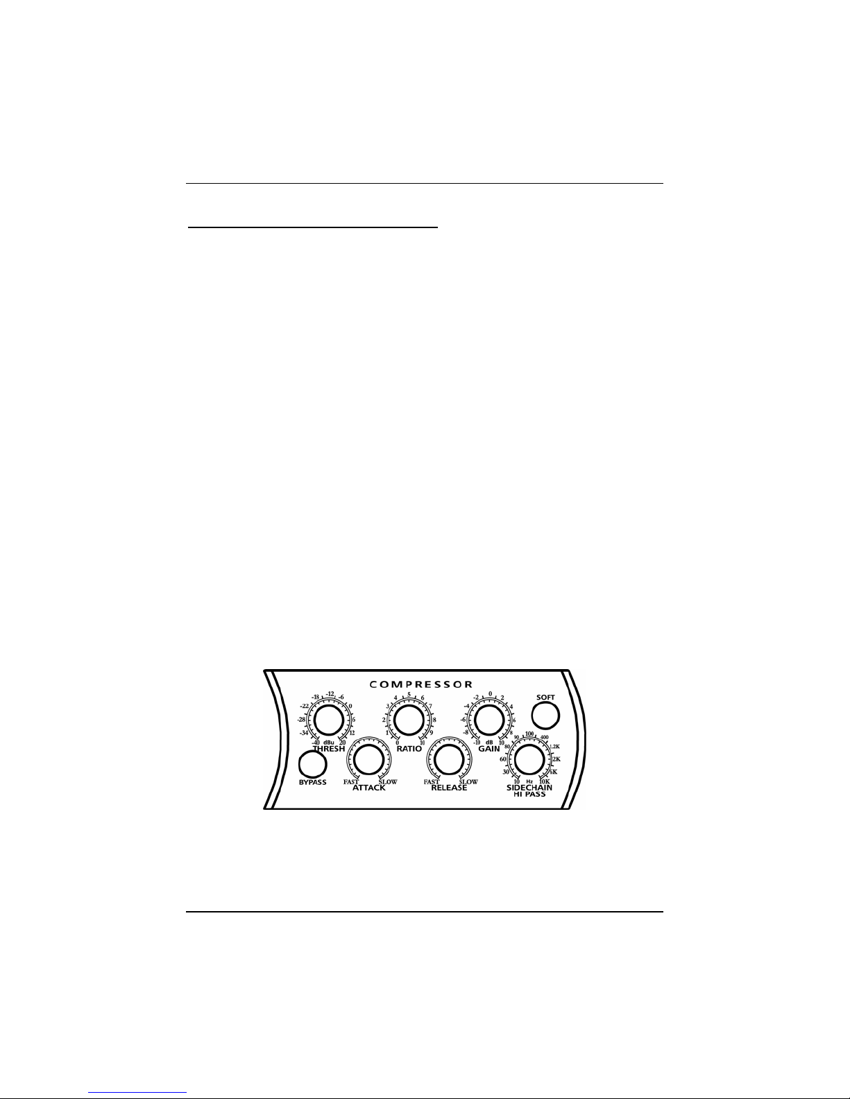
2.3 COMPRESSOR
THRESHOLD: Sets the level at which compression begins. When the signal
is above the Threshold setting, it becomes ‘eligible’ for compression.
Este manual sirve para los siguientes modelos
1
Tabla de contenidos


