ESBE T4 Guía

For underoor heating with thermostatic
mixing valve.
ESBE T4 Pump Control
Set Installation and
Commissioning
Manual

2
Boxed and pre-assembled ready for
installation, including:
- Esbe Thermostatic mixing valve, adjustable from
20°C to 55°C (BS2164)
- Temperature gauge measuring mixed water
- 'A' rated Stuart Turner 25/6 Pump
- 1" Male swivel joints for fast connection to 1" Female
manifold tappings
- Nickel plated for improved appearance
- In-built non-return valve in ow elbow to enable
simple system lling when commissioning
- 3/4" Female BSP ow and return connections
- Suitable for any manifold with connections on
210mm centres (Also available in 200 and 225mm)
- Fully reversible oering with side or bottom entry
primary connections
2

3
1. General
1.1 Provides control of ow and return water temperature in an underoor heating
system. Pre-assembled and tested to ensure that it can be tted with minimum
on-site labour required and commissioned immediately once tted.
1.2 Designed to connect to the right-hand side of a manifold with 200mm as standard
(210 / 225mm optional) between the centres of the ow and return arms. The control
group can also be altered to t to the left-hand side of a manifold simply by turning the
control group elbows through 180 degrees, using the union ttings at the top and
bottom of the pump. The pump motor may need to be rotated through 180 degrees to
minimise the space occupied by the control group. Primary connections can be applied
from the side or bottom of the control pack.
2. Connections & Dimensions
3. Technical Data
Maximum static pressure 10 Bar
Maximum dierential pressure 3 Bar
Maximum temperature 95°C
Operating temperature range Adjustable between 20°C to 55°C (BS2164)
Inlet connections 2 x 3/4" BSPF
Outlet connections 2 x 1" BSPM swivel joint
Overall dimensions (mm) 290 h x 150 w x 140 h (Excluding item.3)
Kvs 3.4
Material Nickel plated brass
Power 18kW
Item Description Qty
1 Stuart Turner 25/6 Pump 1
2 ESBE Thermostatic Mixing Valve 1
3 Flow / Return Elbow 1
4 2mm Rubber Washer 2
5 1 1/2” Rapid Connection Nut 2
6 Elbow Flanged 1
7 3/4” Female BSP Flow and Return 2
8 3/8” Pocket 1
9 Temperature Gauge 1
10 Manifold Centre Distance Spacer 1
RReturn from Manifold / Flow to Heat
Source NA
H Flow from Heat Source NA
282
70
156
200*
1”M BSP
3/4”F BSP
*STANDARD CENTRE DISTANCE. 210MM & 225MM ALSO AVAILABLE

4
4. Pre-Installation
Prior to installation, manifold conguration must be determined as left or right handed.
5. Installation
5.1 Carefully remove from the packaging and check that all components are in place and that
nothing has been damaged during delivery.
5.2 The pump mixer is supplied for connection to the right-hand side of the manifold but can
be altered very simply for connection to the left-hand side. (See above)
5.3 To change orientation:
a) Remove swivel nut (7) from the TMV and move to opposite connection.
(These joints use o-ring seals and should not be overtightened)
b) Loosen the pump rotating nuts (5) on the elbow (6) and rotate through 180 degrees.
Re-tighten nut (5) after rotation.
5.4 Pipe connection orientation can be altered to suit using ow / return elbow (3) (supplied
loose) tted in either ow or return.
5.5 A swivel joint is tted to each side of the control group for connecting to the 1” F manifold
tappings. Carefully oer up and screw the swivel joint threads evenly into the
manifold using a 37mm A/F spanner: the use of a 31mm A/F spanner will also ensure
that the connection to the pump mixer is kept tight. The joints use o-ring seals and care
should be taken not to over-tighten them.
5.6 Once connected, nish securing the manifold and large area mixer to the wall if not
already completed.
5.7 The primary ow and return pipework can now be connected to the 2 x 3/4” F connections.
The ow connection is at the H and the return connection is at the R. It is recommended
that ball valves are used to isolate this pipework where it is connected to the pump mixer.

5
6. Commissioning
6.1 Filling the UFH system - The inbuilt non-return valve in the ow elbow allows you to ll
the circuits from the upper ow rail drain and ll valve only.
Be aware that you cannot get the benet of this feature when lling via the primary ow and
return connections or the lower manifold rail drain and ll valve.
6.2 The mixer, manifold and underoor circuits can now be lled and commissioned in
accordance with the manifold instructions. Prior to lling, a nal check of all joints should
be made to ensure no connections have loosened during transit.
6.3 The pump is supplied with a pre-connected 1m long 3-core lead assembly ready for
connection to the electrical control system. Ensure that the pump is lled and vented,
operate the control system to call for heat then select the desired pump setting.
The ESBE T4 control pack comes pre-assembled ready for installation, please ensure the
pump connections are tightened before commissioning. These connections are equipped
with EPDM seals.
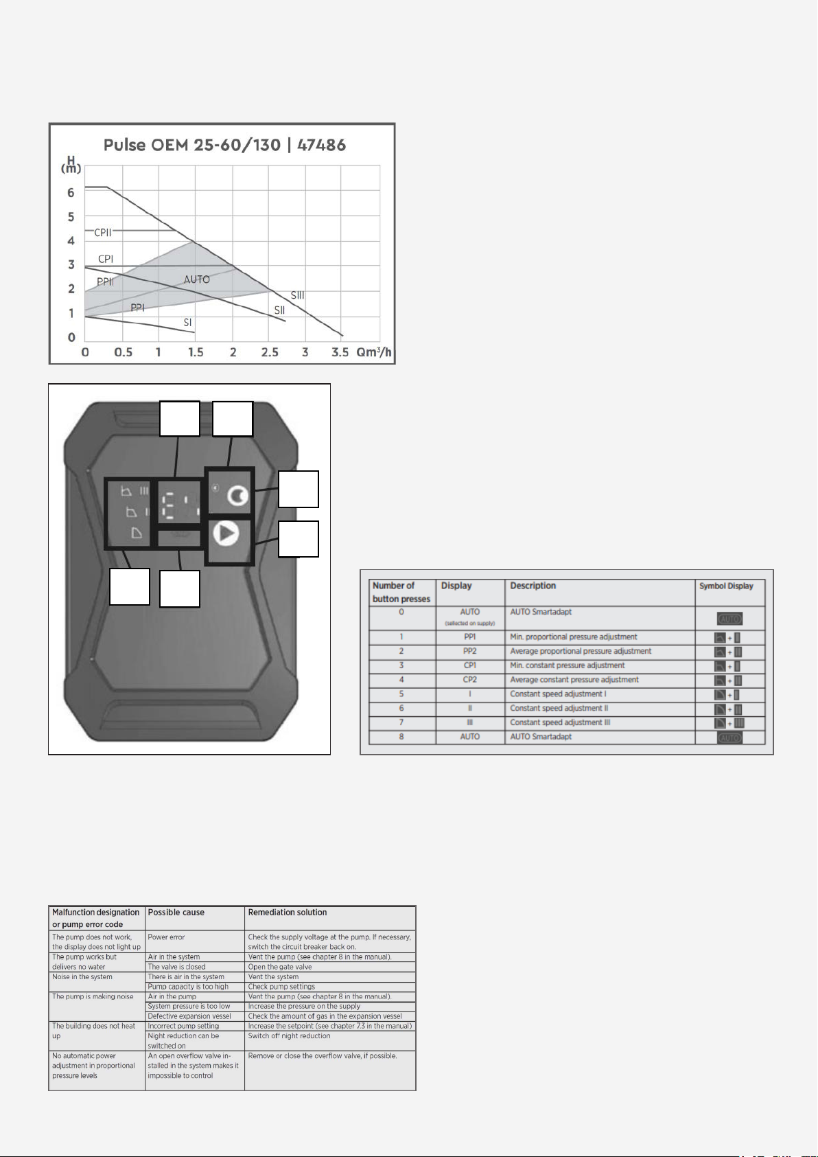
7. Pump Settings
Buttons
All pump functions can be controlled with two buttons. The button switches the night
reduction function on and o. The button controls the operating modes. The selected
operating mode is shown in the clear eld of the LED indicator.
Temperature Setpoints in °C 20 25 30 35 40 45 50 55
5
Service Mode, setting the capacity range
The capacity range can be changed to 4m or 6m in
service mode.
• Pump must be disconnected from the 230V mains
voltage for at least 15 seconds
• Connect the pump to the 230V mains voltage
• Press the and buttons simultaneously with 3
seconds
• Release both buttons
• Select the capacity range with the button
• - 4 = 4m
• - 6 = 6m
• Pump must be disconnected from the 230V mains
voltage for at least 15 seconds
• Connect the pump to the 230V mains voltage
6
7. Pump Settings (Continued)
Technical data
6
1 2
3
4
5
6
Malfunctions, causes and elimination
Maintenance work or repair attempts may only be performed by qualied personnel. Before
conducting maintenance, cleaning and repair work, disconnect the system from the power
supply and secure it against neing switched on again by unauthorized persons. At high water
temperatures and system pressures, wait for the pump to cool down beforehand. There is
risk of burns!
Control panel and LED display
1. Display of energy consumption in watts
2. Automatic night reduction display
3. Button for activating the automatic night reduction
4. Operating mode selection button
5. Display for activated AUTO Smartadapt mode
6. Display of the nine operating levels (characteristics)
of the pump

7
Our other UFH products:
Single-loop Pump Pack
The single-loop assembly is designed to connect
to new and existing heating systems with 15mm
compression connections for the flow and return.
The temperature switch supplies power to the pump
and will remain open until the existing heating
system water is above 40°c. Following this, the
switch will close activating the 'A' rated pump, which
will allow the TMV to mix flow and return to the
required UFH temperature. Unit is suitable for use
with floor areas of 60–90sqm or max output of 5kW.
Heat Pump Pack
The heat pump model is a pre-assembled unit that
is designed to be connected (via ball valves) to the
manifold. The unit is for use in applications where
water temperature controls are not required.
This is typically seen where heat pumps or low
temperature systems are utilised.
The unit includes an ‘A’ rated energy efficient pump
and is suitable for use with floor areas up to 250sqm
or a maximum output of 20kW. Primary flow and
return connections can be made from the side or
the bottom of the unit. This can also be mounted on
either the left- or right-hand side of the manifold.
7

Tabla de contenidos
Otros manuales de Unidad de control de ESBE


Manuales populares de Unidad de control de otras marcas

Festo
Festo Compact Performance CP-FB6-E Manual de lista de piezas

Elo TouchSystems
Elo TouchSystems DMS-SA19P-EXTME Manual de usuario

JS Automation
JS Automation MPC3034A Manual de usuario

JAUDT
JAUDT SW GII 6406 Series Guía rápida

Spektrum
Spektrum Air Module System Manual de usuario

BOC Edwards
BOC Edwards Q Series Manual de usuario


