ERT VIPER Manual de usuario

US EPA Environmental Response Team
User Manual For
Viper - Smart Gateway
ERT Support: 800-999-6990 Page 1
ERT
USER MANUAL
for
V
IPER –SMART GATEWAY

US EPA Environmental Response Team
User Manual For
Viper - Smart Gateway
ERT Support: 800-999-6990 Page 2
TABLE OF CONTENTS
O
VERVIEW
.................................................................................................3
S
MART
G
ATEWAY
B
ENEFITS
........................................................................3
O
THER
D
IFFERENCES
..................................................................................3
S
MART
G
ATEWAY
H
ARDWARE
I
NFORMATION
.................................................4
EXTERNAL PORTS .................................................................................................................. 4
ANTENNAE AND SIM CARDS ................................................................................................ 5
Interpreting LEDs on the Gateway: ................................................................................................................... 5
GATEWAY NAME AND POWER SWITCH .............................................................................. 6
INTERNAL EQUIPMENT .......................................................................................................... 7
U
SING THE
S
MART
G
ATEWAY
......................................................................8
Logging in to the Internal Laptop .......................................................................................... 8
Windows Remote Desktop Connection from within the EPAERT1 WiFi Network ............................................. 8
Windows Remote Desktop Connection via the Internet .................................................................................... 8
External Monitor, Keyboard and Mouse ............................................................................................................ 9
Internal Touch Screen Display – Last Resort .................................................................................................... 9
Troubleshooting the Internal Laptop (Motherboard) ......................................................................................... 10
Troubleshooting Remote Desktop Connection to the Smart Gateway ............................................................. 11
Logging in to the Cradlepoint Router .................................................................................. 13
Quick Reference Sheet for Accessing the Smart Gateway Laptop & Cradlepoint ......... 13
Section 1 – Using the External Ports on the Smart Gateway ............................................ 14
Using COMx (Traditional LINC Cable Port) ...................................................................................................... 14
Troubleshooting Serial (COM Port) Connections ............................................................................................. 18
Using the USB Ports to Connect Instruments – Serial to USB (i.e., DustTraks) ............................................... 19
Using the Ethernet (RJ45) Port (SPM Flex) ..................................................................................................... 20
Section 2 – Smart Gateway MeterApp ................................................................................. 21
Smart Gateway Sensors .................................................................................................................................. 21
Additional Signal and SINR Information ........................................................................................................... 22
Troubleshooting the Smart Gateway MeterApp ............................................................................................... 22
Adding the Smart Gateway MeterApp to a Survey Controller Run ................................................................... 24
Section 3 – Smart Gateway WiFi and Security ................................................................... 27
Disabling/Enabling WiFi ................................................................................................................................... 27
Changing WiFi Network Name (SSID) in the Gateway..................................................................................... 29
Disabling WiFi Security .................................................................................................................................... 31
Enabling WiFi Security ..................................................................................................................................... 32
Section 4 – Cradlepoint GPS Settings ................................................................................. 33
Overview .......................................................................................................................................................... 33
Troubleshooting the Cradlepoint GPS Settings ................................................................................................ 33
Section 5 – Internet Sources ................................................................................................ 36
Internal SIM Card ............................................................................................................................................. 36
External WiFi Source ........................................................................................................................................ 37
Ethernet Connection – Hard Wired .................................................................................................................. 37
Troubleshooting WiFi and Ethernet internet sources ....................................................................................... 38
Section 6 – Directly connecting a RAE Host to the Smart Gateway ................................. 40
Overview .......................................................................................................................................................... 40
Install ProRAE Guardian Software ................................................................................................................... 40
Attaching ProRAE Host to the Smart Gateway ................................................................................................ 40
Configuring ProRAE Guardian ......................................................................................................................... 41
Configuring Viper Survey Controller ................................................................................................................. 44
Configuring PRG2CAP ..................................................................................................................................... 44
Creating a Survey Controller Run with ProRAE Guardian Instruments ............................................................ 45
Tips, Tricks and Troubleshooting ..................................................................................................................... 45

US EPA Environmental Response Team
User Manual For
Viper - Smart Gateway
ERT Support: 800-999-6990 Page 3
OVERVIEW
The Smart Gateway can be used as a traditional gateway following the normal Viper user guide
procedures or you can choose to transition tasks where you previously used a laptop or a Virtual
Machine to now directly run on the gateway. There is also an opportunity to connect instruments
directly, eliminating the need for LINCs.
SMART GATEWAY BENEFITS
Longer Battery Life (15 hours)
Internal Laptop – Run Survey Controller Locally, eliminating need for VM & potential to run other
data acquisition software in parallel (ProRAE Guardian)
MeterApp To Monitor Battery Life, Gateway Temperature, Disk Space & RAM
External serial Port can be used to directly connect an instrument without a LINC
Connect additional instruments via USB/Serial connections and virtual com ports
Auto-Detects SIM Card Provider and Selects Appropriate Firmware
Built-In GPS – Coordinates Distributed to All Attached Instruments
OTHER DIFFERENCES
No Mesh Radio – (external add-on module under development by Safe Environmental Engineering)
Ability To Use Multiple Internet Sources with Private IP Addresses and Still Push Data to
Deployment Manager (Technically Advanced Feature).
Potential for Bluetooth Instrument Connections

US EPA Environmental Response Team
User Manual For
Viper - Smart Gateway
ERT Support: 800-999-6990 Page 4
SMART GATEWAY HARDWARE INFORMATION
EXTERNAL PORTS
1. HDMI Monitor Port
Connect an external monitor to the internal
laptop.
2. RJ45 (Ethernet) Port
Can be configured as LAN or WAN
a. LAN – Connect instruments with
Ethernet Outputs (i.e., SPM Flex)
b. WAN – Obtain internet access from
an external network via hardwired
Ethernet (home/work internet
connection).
3. USB Ports
Can connect external keyboard and mouse
to to the internal laptop or can be used to
connect Serial (RS-232) instruments.
4. Traditional LINC Cable port (Gen 3 and
Above)
Connect an instrument using a traditional
LINC cable. The MeterApp will be configured
for a Serial connection. The port label will
indicate the Com Port number assigned to
that connection.
5. Smart Gateway External Power Connection
Connect the power cord to run the gateway with power or to charge the internal battery. The internal
battery lasts 15 hours with the internal monitor off. Battery strength can be monitored via the Smart
Gateway MeterApp.
6. Port is currently not active
It is expected that in the future, this port will be used for connecting instruments that output data via
voltage.
1 2 3
4 5 6
NOT ACTIVE
FUTURE VOLTAGE
PORT

US EPA Environmental Response Team
User Manual For
Viper - Smart Gateway
ERT Support: 800-999-6990 Page 5
ANTENNAE AND SIM CARDS
To insert the SIM card, remove the two screws on the SIM door, install the SIM in either slot, put the
screws back in. (Gateway will not boot up if the SIM port screws are out)
FIRST TIME INSTALLATION: When installing your SIM card for the first time, leave the gateway
powered on for several hours in order to allow the SIM card to obtain its IP Address and register
itself on the internet.
Interpreting LEDs on the Gateway:

US EPA Environmental Response Team
User Manual For
Viper - Smart Gateway
ERT Support: 800-999-6990 Page 6
GATEWAY NAME AND POWER SWITCH
Gateway Name:
The Gateway Name is labeled on the side of the
gateway with the handle. The gateway name is
EPAERTXXX where X represents a unique number.
Power Button:
Depending on the build of your Smart Gateway, the
power switch can be either a toggle switch or a push
button. The toggle switch is convenient in that it
allows the gateway to remain on when switching
between shore power and battery. However, it is easy
to accidentally turn the switch on/off when picking up
the gateway or when packing the gateway in a case. If
it is necessary to ship the Gateway, it is recommended
that a piece of tape be applied over the switch to keep
it in the off position during shipping.
Motherboard Reset Port:
There is a port covered by a screw that allows for a
hard-reset of the gateway motherboard. See the
troubleshooting section later in this manual for
additional details.

US EPA Environmental Response Team
User Manual For
Viper - Smart Gateway
ERT Support: 800-999-6990 Page 7
INTERNAL EQUIPMENT
The photo here is for illustration
Purposes only. There is typically NO
NEED to open a Smart Gateway
1. Cradlepoint IBR900LP6 Router
https://cradlepoint.com/products/cor-ibr900-series
- Auto-detects SIM provider and selects
appropriate Firmware
- Can obtain internet access via Ethernet and
WiFi in addition to Cellular signals
- Obtains and provides GPS for instruments
that are directly connected to the gateway
- Broadcasts WiFi (EPAERT1)
2. Touch-Screen Monitor & Gateway Battery
- Access to the internal laptop if Remote
Desktop Connection and External
Monitor/Keyboard/Mouse are not working.
Behind the touch-screen is the gateway’s
battery (black).
3. Internal Computer Info
- Windows 10 – 64 Bit 4 GB RAM
- 64 GB Hard Drive (40 GB
Free)

US EPA Environmental Response Team
User Manual For
Viper - Smart Gateway
ERT Support: 800-999-6990 Page 8
USING THE SMART GATEWAY
The Smart Gateway contains both a Cradlepoint Router and a laptop. Login to the laptop to run Viper
Survey Controller locally. Login to the Cradlepoint Router to determine internet connection status and to
change internet configuration.
Logging in to the Internal Laptop
The internal laptop in the Smart Gateway serves a few purposes. First, the laptop acts as its own ‘virtual
machine’. Viper Survey Controller can be configured and managed on the Smart Gateway, and as long as
a SIM card is installed, Survey Controller can be managed remotely – similar to an ERT-provided Virtual
Machine. There is also a ‘Smart Gateway MeterApp’ that runs on the internal laptop. This ‘MeterApp’
monitors the performance of the Smart Gateway, including metrics such as temperature, battery life, disk
space, etc.
The recommended option for logging in to the Smart Gateway’s internal laptop is through Windows Remote
Desktop Connection from another laptop or tablet.
Windows Remote Desktop Connection from within the EPAERT1 WiFi Network
The steps below illustrate how to access the Smart Gateway laptop from the EPAERT1 WiFi Network
Power on the Smart Gateway. Wait at least 5
minutes before trying to login
Connect a laptop (or mobile device capable of
running Remote Desktop Connection) to the
EPAERT1 WiFi network
Run Windows Remote Desktop Connection
Computer Name = 192.168.4.4
Username = \LifelineSmartGateway
Click the Connect button
Contact[email protected]toobtainthe
password
Enter the password obtained. Click OK.
Click Yes past the security warning screen
The Smart Gateway Windows 10 screen will be displayed in the Remote Desktop window. Operate the
Smart Gateway laptop as you would any other laptop.
Windows Remote Desktop Connection via the Internet
The steps below illustrate how to access the Smart Gateway laptop using Windows Remote Desktop
Connection from a laptop that is not on the EPAERT1 WiFi network. This method requires that the Smart
Gateway has a SIM card installed and the SIM card is using a Public IP Address. If you are unfamiliar with
determining the IP Address of the SIM card installed, refer to Section 10/Step 5 of the ERT Viper User
Guide or contact ERT Support for assistance.
Power on the Smart Gateway. Wait at least 5 minutes before trying to login
Gateway SIM must have a public IP Address

US EPA Environmental Response Team
User Manual For
Viper - Smart Gateway
ERT Support: 800-999-6990 Page 9
Using an internet-connected laptop or mobile device
(not on the EPAERT1 WiFi network), run Windows
Remote Desktop Connection
Computer Name = the EXTERNAL gateway address
followed by :7000 (i.e.,
EPAERT265.SAFEENV2.COM:7000)
Username = \Lifeline SmartGateway
Contact[email protected]toobtainthepassword
Enter the password obtained. Click OK
Click Yes past the security warning screen
The Smart Gateway Windows 10 screen will be
displayed in the Remote Desktop window. Operate the Smart Gateway laptop as you would any other
laptop.
External Monitor, Keyboard and Mouse
Connect an external HDMI monitor to the HDMI port on the back of the Smart Gateway
Connect a keyboard and mouse to the USB ports on the back of the Smart Gateway
Power on the Smart Gateway
The Smart Gateway Windows 10 screen will be displayed on the external HDMI monitor
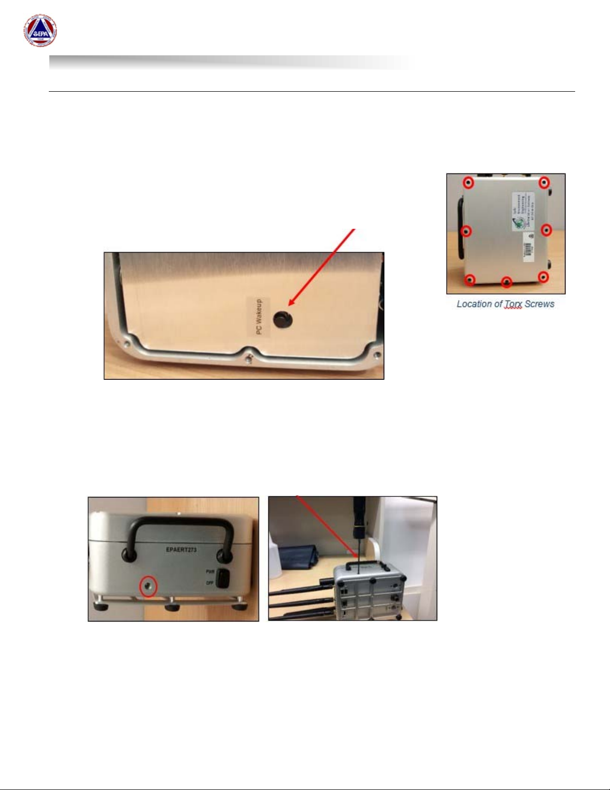
Internal Touch Screen Display – Last Resort
Remove the 7 torx screws holding the Gateway closed
Open the Gateway
The monitor is a touch screen with a virtual keyboard
If the monitor doesn’t wake-up when you touch the screen, use the ‘PC
Wakeup’ button located inside the Gateway below the Cradlepoint router.
US EPA Environmental Response Team
User Manual For
Viper - Smart Gateway
ERT Support: 800-999-6990 Page 10
Troubleshooting the Internal Laptop (Motherboard)
In some instances, the internal laptop doesn’t boot up at all. There are two (2) options for resetting the
laptop.
Option 1:
Remove the 7 torx screws holding the Gateway closed
Open the Gateway and power it up
Depress the ‘PC Wakeup’ button for 30 seconds
Release the ‘PC Wakeup’ button and power the gateway off and on
Option 2:
With the Smart Gateway powered up, back out the torx set screw (circled below in red). After removing
the screw, insert a device that is long enough to depress the interal reset button for 30 seconds. The
reset button is small and will only depress a tiny bit. After 30 seconds, stop depressing the reset button
and remove the device being used. NOTE: The torx wrench from option 1 above can be used to reset
the laptop.
Power the Smart Gateway off and on.
NOTE: The port may not directly line-up with the motherboard reset switch. Contact ERT Support if
you are not successful with Option 1 and/or 2.
Tabla de contenidos
Manuales populares de Puerta de otras marcas

LST
LST M500RFE-AS Manual de usuario

Kinnex
Kinnex Media Gateway Manual de usuario

2N Telekomunikace
2N Telekomunikace 2N StarGate Manual de usuario

Mitsubishi Heavy Industries
Mitsubishi Heavy Industries Superlink SC-WBGW256 Manual de usuario

ZyXEL Communications
ZyXEL Communications ZYWALL2 ET 2WE Manual de usuario

Telsey
Telsey CPVA 500 - SIP Manual de usuario


