Erhardt+Leimer OL 80 Manual de usuario

Description B
CCD array camera OptoLine OL 80..
BEA--220265-EN-04
en
1. General
instructions 2
2. Typereferences 2
3. Function 3
4. Cameracontrols 6
5. Assembly 7
5.1 Determiningscanningdirection 7
5.2 Determiningcamerameasuringrangeanddistance
betweencameraandweb 7
5.3 DeterminingthelighttransmittersizeanddistanceM
betweenthelighttransmitterandcamera 8
5.4 Cameraassembly 9
5.5 Lighttransmitterassembly 9
5.6 Determiningthebackground 10
5.7 Mountsupportroller 10
6. Installation 11
7. Commissioning 11
7.1 Positioncamera 12
7.2 CheckwiringCheckwiring 12
7.3 Checksupplyvoltage 12
7.4 SetcameraCANaddress 12
7.5 Positionthewebedgeinthecameravisualrange 13
7.6 Setthecameraapertureandfocusing 13
7.7 Cameraconguration 16
7.8 Cameracalibration 20
7.9 Widthmeasuringfunctioncalibration 23
7.10Performapplication-dependentsettings 23
8. Operation 26
8.1Specifysetpositionvalueforguiders 26
9. Camerastart-upresponse 27
10.Paramterlist(Excerpt) 28
11.Errormessages 30
12.Maintenance 31
13.Technicaldata 31

BPage2 BEA--220265-EN-04
CCDarraycameraOptoLineOL80..
1. General
instructions
1.1 Description ThisdescriptionappliesforallCCDarraycamerasintheOL80..se-
ries.Itexplainsthestandardoperationforwidthmeasuringandweb
guidingwithoneortwocamerasonamovingweb.
Keepthedescriptioninasafeplace,accessibletopersonnelatall
times.
Thedescriptionispartofthepackagesuppliedandshouldberead
carefullypriortoassembly,operationandmaintenancework.
➜jobstobeperformed
important information and instructions
TheCCDarraycameraOptoLineOL80..shouldonlybeoperated
byqualiedpersonnelorsuitablyinstructedpersons.
CCDarraycamerasintheOL80..seriesareonlydifferentiatedby
theirvariouslenses(measuringranges).Thefunctionofthecameras
isidentical.Thersttwodigitsofthetypereferenceindicatethecam-
eraresolution(80=8192),thethirdandfourthdigits,thelensfocal
length.
Example:OL8028
focallength28mm
1.2 Explanation of symbols
1.3 Operation
2. Type references
BEA--220265-EN-04 BPage3
CCDarraycameraOptoLineOL80..
3. Function
3.1 Purpose
3.2 Design
TheCCDarraycameraOptoLineOL80..wasdevelopedforcon-
tact-freepositionmeasuring.Itdetectsthepositionofcontrasts(edg-
es,lines,utesorgrooves)onamovingweb.Themeasuringresult
canbeusedforwidthmeasuring,webguiding,followingupactuators
ortoolssuchascuttersetc..
Inthisdescriptionthecameraandstandardoperationforwidthmea-
suringandwebguidingwithoneortwocamerasisexplained.Spe-
cialisedapplicationsdesignedbyE+Laredescribedseparatelyinthe
systemspecicationsoroperatinginstructions.
Awidth measuring systemconsistsof:
- oneorseveralcameras
- asetofcables
- oneortwolighttransmitters
- aDO002.remotedisplay
Aweb guiding systemconsistsof:
- oneorseveralcameras
- asetofcables
- oneortwolighttransmitters
- anE+Lcontrollerwithcommandstation
3.3 Operating principle
Frontlighting Backlighting
Scanningmethodes Twodifferentscanningmethodsareusedtodetectcontrasts,front-
lightingandbacklighting.Themethodapplieddependsontheindi-
vidualjob.
Withthe frontlighting methodthelighttransmitterandcameraare
onthesameside,eitheraboveorbelowtheobject.Thecamera
catchesthelightreectedbytheobjectfromthelighttransmitter.
Whenfrontlightingisused,outeredgesandlines,utesorgrooves
canallbedetected.

BPage4 BEA--220265-EN-04
CCDarraycameraOptoLineOL80..
Withthebacklighting methodthelighttransmitterispositioned
behindtheobjecttobescanned,asseenfromthescannedobject.
Inthecaseofnon-transparentmaterials,onlytheouteredgesare
detected.
Thefollowingappliesforbothmethods:
Whetheroneortwocamerasareusedtoestablishthepositionde-
pendsontheresolutionandwebwidthrequired(seeblockdiagram).
Whatisimportantisthatwhenwidthmeasuringorwebguidingwith
onecamera,bothwebedgesarealwaysinthecameravisualrange.
Whenwidthmeasuringorwebguidingwithtwocameras,oneweb
edgeeachmustbeinthecameravisualrange.
Thecenterpieceofthecameraisachargecoupleddevicewith2048
pixels.Theindividualpixelsconvertthelightshedintosignalvoltag-
es.Contrastchangesinthecamerameasuringrangesuchasaweb
orprintedlineonawebcauseachangeinthevoltage.The
cameracandetectupto30contrastchangesinitsmeasuringrange,
regardlessofwhetherthesearecausedbyoneorseveralwebs.See
g.onpage5.
Amaximumof8measuringvaluescanbeoutputonthebasisofthe
positionsrecorded.Ameasuringvalueisacontrastposition(e.g.the
webedgeposition)orthecenterbetweentwocontrasts(e.g.theweb
orlinecenterposition).
Thebuilt-inlightcontrollermakesthecamerapracticallyimpervious
tosoilingcausedbydustandenvironmentalfactorssuchassteamor
ambientlightuctuations.
Alldatatothecamera(camerasettings,measuredvalueselection)
andfromthecamera(measuredvalueposition,errormessages,
statusinformation)aretransferredviaaCANinterface.TheCAN
controllerisbuiltintothecamera.Thein-houseE+Lprotocolisused
ontheCANbus.Couplingtootherbusesorunitinterfacesises-
tablishedviaspecialinterfacemodulesthatcanbeattachedtothe
CANbus.Twokeysanda16-bitLEDdisplayareavailableforbasic
operatingfunctions,settingtheCANaddress,focusingthecamera
anddisplayingthemeasuredvalueposition.Furthersettingsareper-
formedviaanE+LcommandstationDO..orRT...
*CCD=Charge-Coupled-Device

BEA--220265-EN-04 BPage5
CCDarraycameraOptoLineOL80..
Frontlightingprinciple
Pixel1
CCD-camera
Scanonoscilloscope
Edge Printedline(dark)
Lighttransmitter
Web(light)
CCDcamera
visualrange
1Edge
2/3Line
1
Background
2 3
2048 Scanningdirection

BPage6 BEA--220265-EN-04
CCDarraycameraOptoLineOL80..
4. Camera controls LED display
Innormalmode,theLEDdisplayindicatesthepositionofthemea-
suredvalue(e.g.thewebcenter)inthecamerameasuringrange.In
theeventofmalfunctions,itindicatesvariouserrors,seeerrormes-
sagessection.
Arrow
TheLEDonthearrowindicateswhenthecameraisreadyforop-
eration.Whenconnectedtothepower,itlightsupreduntilcamera
initializationiscomplete.Whenthecameraisreadyforoperationit
lightsupgreen.
GRP key
UsetheGRPkeytosetthegroupnumberandfocusthecamera,see
the"SettingthecameraCANaddress"and"Focusingthecamera"
sections.
DEV key
UsetheDEVkeytosetthecameradevicenumber,see"Settingthe
cameraCANaddress"section.
TheDEVkeyisalsousedtosetwhichmeasuredvalueistobein-
dicatedontheLEDdisplay.PressandholddowntheDEVkey.The
addressofthemeasuredvaluecurrentlybeingdisplayedisindicated.
Theaddressesofallconguredmeasuredvaluesaredisplayedin
sequenceat5secondintervals.Releasethekeyoncetheaddressof
therequiredmeasuredvalueappears.
Other settings by the E+L Setup Editor.
The setup editor is a software tool for calibrating and con-
guring E+L CAN modules such as camera OL 80.. . In setup
mode parameters can be displayed and some changed as
well. Setup mode is accessed via a command station DO ....
or operator panel RT .... . See description "CAN-Bus, serial
bus and setup editor".
If the cameras are used only for width measuring, i.e. the
system only has a remote display DO 002. (no E+L controller
DC..), the device number of the remote display must always
be 5 (device 5). Only then can the setup editor be started.
Cameracontrols

BEA--220265-EN-04 BPage7
CCDarraycameraOptoLineOL80..
5. Assembly Please observe the locally applicable and professional safety
and accident prevention regulations.
Assembly procedure:
5.1 Determinescanningprocedure
5.2 Determinecamerameasuringrangeanddistancebetween
cameraandweb
5.3 Determinethesizeofthelighttransmitterandthemaximum
distancebetweenthelighttransmitterandcamera
5.4 Assemblecamera
5.5 Assemblelighttransmitter
5.6 Determinebackground,mountblackscreenasrequired
5.7 Mountsupportrollerasrequired
Selectfrontlightingtoscanlinesortransparentwebs,edgeson
opaquewebsshouldbescannedusingbacklighting.Inbordercases,
thesuitablescanningprocessshouldbeselectedbytrialanderror.
ThedistanceKbetweenthecameraandwebinuencesthecamera
measuringrange:
- theshorterthedistance,thesmallerthemeasuringrange
- thesmallerthemeasuringrange,themoreprecisethemeasure-
ment(resolution)
Thefollowingdiagramwillhelpyoudeterminethedistancebetween
thecameraandwebforassemblypurposes.
The dimensions in the diagram are approximate.
5.1 Determining scanning
direction
5.2 Determining camera mea-
suring range and distance
between camera and web
K
OL 8024
OL 8028
Measuringrange
incms
Distancebetweencamera
andwebKincms
OL 8050
Web
Distancebetweencameraandweb

BPage8 BEA--220265-EN-04
CCDarraycameraOptoLineOL80..
5.2.1 Systems with one camera:
5.2.2 Systems with two cameras:
The web must never lie outside the camera measuring range.
TheE+Llighttransmitterisavailablewithone uorescenttube
(FS16.1) andwithtwouorescenttubes(FS16.2).Ifsufcient
spaceisavailable,thelighttransmittershouldalwaysbeusedwith
twouorescenttubes.
Whenselectingthelighttransmitter,pleaseobservethefollowingcri-
teria:
- distanceKbetweenthecameraandweb
- distanceLbetweenthelighttransmitterandweb
- thelighttransmitteroperationalrange
measuringrange=max.webwidth+max.webmovement**+safety*
measuringrange=max.webwidth-min.webwidth+max.webmovement**+safety*
*Dependingontheapplication,asafety
clearanceof50-100mmmustbeal-
lowedforineachcase.
**Onapplicationswithanactuating
element,e.g.pivotingframe,thestroke
mustbetakenintoaccountwithregard
towebmovement.
5.3 Determining the light
transmitter size and dis-
tance M between the light
transmitter and camera
CCDcamera
...notusable
100mm...
Operationalrange
Web
Lighttransmitter
CCDcamera
visualrange
Distances:camera-Lighttransmitter-Web
DistanceKbetweenthecameraandwebisdeterminedbythemea-
suringrange.DistanceLbetweenthelighttransmitterandwebdeter-
minesthescanningprocess.
Whenusingfrontlightingthedistancebetweenthelighttransmitter
andthewebshouldbeasshortaspossibletocapturethemaximum
amountoflight.Thefollowingappliesforbacklighting;theshorter
thedistancebetweenthelighttransmitterandtheweb,thegreater
thedangerofdirtbeingsharplydepictedonthelighttransmitter,
causingincorrectmeasurements.Werecommendaminimumdis-
tanceof100mm.
The camera visual range must always be located in the light
transmitter operational range. On E+L light transmitters, the
outer 100 mm are not usable for the cameras.
Measuringrange
2

BEA--220265-EN-04 BPage9
CCDarraycameraOptoLineOL80..
Thelongerthelighttransmitter,thegreaterthegapwillbe.Themaxi-
mummountingdistancecanbecalculatedasfollows:
Ifthecameralooksdownonthewebfromabove,itshouldbemount-
edsothatthearrowonthecameraoperatingcontrolspointsinthe
directionofwebtravel.Ifthecameralooksuptothewebfrombelow,
thearrowshouldpointintheoppositedirectiontothatofwebtravel.
OncamerasystemsdesignedbyE+L,themodulereferencemust
alsobechecked(e.g.B2).Theblockdiagramspeciesexactly
whichcamerashouldbemountedonwhichsideoftheweb,seen
fromthedirectionofwebtravel.
TwodifferentE+Lsupportsareavailableformountingthecamera,
seeattacheddrawing.
We recommend you pin the supports once the camera has
been positioned (7.1 commissioning).
Howthelighttransmitterismounteddependsonthescanningpro-
cessimplemented.
M= Max.mountingdist.camera-lighttransmitterMinmms
a = Lighttransmitteroperationalrangeinmms
b = CCDelementlength=28,67mm
f = Lensfocallength(24,28or50mm)
Verticalwebtravel Horizontalwebtravel
5.4 Camera assembly
5.5 Light transmitter assembly
Lighttransmitterassemblywith
backlightingprinciple
Lighttransmitterlength Lighttransmitterh Maximummountingdistancecamera-lighttransmitterM
FS16.1FS16.2operationalrange OL8024 OL8028 OL8050
665mm 685mm 450mm 400mm 460mm 830mm
1275mm 1295mm 1050mm 900mm 1050mm 1880mm
1575mm 1595mm 1350mm 1150mm 1340mm 2400mm
M= f(a+b)
b
1. 2. 3.
Whenusing backlightingwerecommendthethreemountingvari-
antsabovetoavoidsoiling.
ThefollowingtableliststhemaximumdistanceofstandardE+L
transmitterstothecamera.

BPage10 BEA--220265-EN-04
CCDarraycameraOptoLineOL80..
Background Background
Web
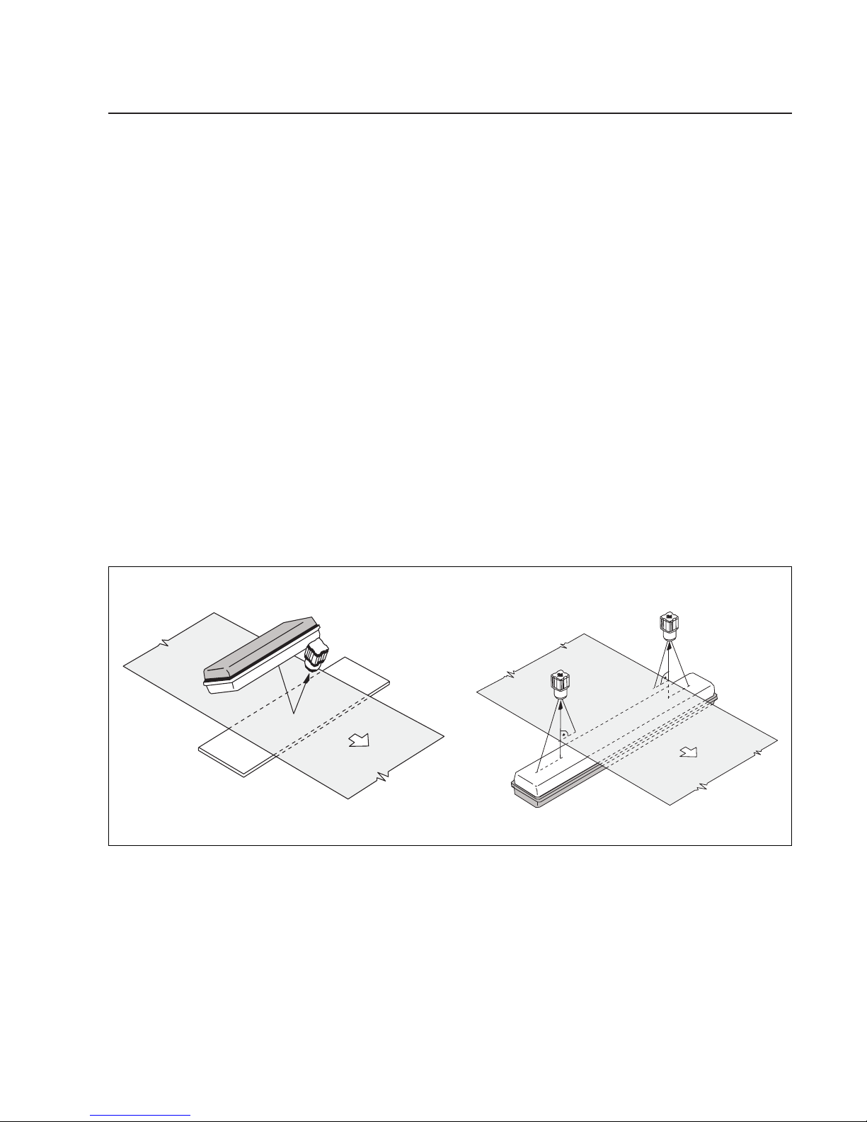
Lighttransmitterassemblywith
frontlightingprinciple
Whenusingfrontlightingthefollowingshouldbeobserved:
- whenscanningtheedgesoftransparentwebs,mountthelight
transmittersothatthemirrorsurfacereectsthelightsentfrom
thetransmitterintothecamera(seeillustrationaboveleft).
- whendetectinglinesandcolourcontrastsontransparentand
opaquewebs,mountthelighttransmittersothatadiffusereec-
tionisproduced.Surfaceglareisavoidedandaclearimageis
produced(seeillustrationaboveright).
When frontlighting, please ensure that the light transmitter is
not in the camera visual range.
Auniformcontrast-freedarkbackgroundisrequiredforfrontlighting.
Youmayhavetomountamattblackpanelbehindtheweb,inthe
cameravisualrange.Thisoptimumcontrasttothewebguarantees
efcientwebedgescanning,inuencesfromexternallightsources
areavoided.
Itmustbeguaranteedthatthewebdoesnotformfoldsorcreases
andthattheedgesdonotturnupasotherwisethelightisreectedat
adifferentanglebythewebandnolongercapturedbythecamera.A
supportrollercanbemountedifnecessary.
Withfront-lightning,thesupportrollershouldbemountedoutsidethe
camerameasuringrange,eitherbeforeorafterthecamera.Seeil-
lustrationonleft.
5.7 Mount support roller
5.6 Determining the back-
ground
Background
Supportroller
Example:frontlighting
Supportrollermountedafterthecamera
Tabla de contenidos


