P315
STAIR INSTALLATION
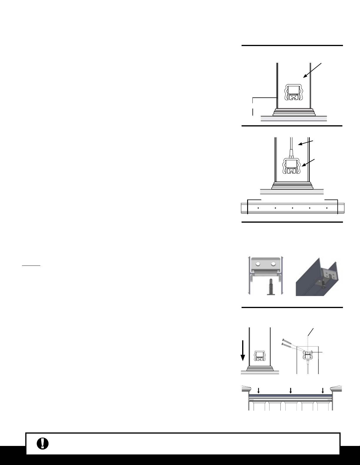
STEP 4
STEP 1
Fairway Architectural Railing Solutions will not be held liable for incorrect or unsafe installations by the installer. It is the installer’s responsibility to secure
proper building permits, review local codes and safety needs and meet or exceed them. The instructions provided by Fairway are a guide and may not
account for every special circumstance. The installer must indentify and execute the installation approach that is appropriate for every application.
STEP 2
STEP 2 - CUTTING RAILS
NOTE: Before cutting rails make sure that the aluminum inserts are properly
positioned within the rail. The deeper channel should always face the pre-drilled
baluster connector holes.
• Lay bottom rail on stair nosing and against side of posts. Make sure that
the baluster spacing is equal distant from posts on each end. Mark the rails
where it intersects with the posts.
•If posts are plumb, the bottom rail, bottom aluminum insert, sub-rail, top rail and deck
board cap rail can be cut to the same length with the same angle. Make sure you are
equidistant from each end.
NOTE: Cut the top aluminum insert a 1/4” shorter for bracket installation.
STEP 3 - INSTALL BRACKETS, BALUSTERS,
& RAIL SUPPORTS
• Place bottom rail inverted on work surface with aluminum insert facing up.
•Bottom Rail Brackets:
Place
b
ottom rai
l bra
cket on
bottom of aluminum insert with
post mounting ange facing upward. Flange should be ush with the end of the
rail. Mark and drill 1/8” hole in center of aluminum insert. Install #10 x 3/4”
mounting screw through bracket.
• Top Rail Brackets: With mounting anges pointing down on end of top aluminum
insert, (deep part facing baluster) nd center of elongated slot and drill a 1/8”
pilot hole. Install two #10 x ¾” screws. Adjust bracket angles if necessary.
• Find center of post/mounting surface and mark center line (Example 4.25” post=
2/18”). Determining your distance off tread nose, lay bottom rail in position and
center the rail with the center line and mark elongated ange slot on post. Drill a
3/16” hole and install #14x1” screw to within 1/8” of surface.
• Cut rail support (foot block) at one end to match stair pitch. Set bottom rail in place
with slotted ange over screw. Measure distance between tread and bottom of rail.
Add 3/4” and cut rail support, cutting one end to match stair angle. Remove bottom
rail and install support through aluminum using #10 x 3/4” screw.
STEP 1 - GETTING STARTED
• Plumb all posts or mounting surfaces. Install post trim at this time.
• Based on local code requirements, determine required bottom rail height off deck
surface to underside of rail.
Sub-Rail Bottom Rail
STEPS 4 & 5
NOTE: Glass stair balusters are designed to work strictly with a rise/run of 30º-34º.
STEP 5 - INSTALL RAIL SECTION
• With sub-rail in place, now install top rail aluminum insert onto sub rail with bracket anges
facing upward towards you. Gently tap aluminum insert into position with rubber mallet.
Aluminum insert snaps into sub rail.
• Find center of post at top rail aluminum insert, pre-drill two 1/8” holes through top rail
brackets into posts and install two #10 x 1-1/4” screws into posts.
• Place deck board (not supplied ), top side down, on a non-abrasive surface. With at side
down, center top rail along length and width of the deck board. Using the provided
hardware, Install two #10 x ¾” screws, side by side, at quarter points along top rail.
• With deck board cap rail installed, carefully snap top rail over aluminum insert. Ensure
that the top rail is seated entirely
STEP 6 - FINISHING STEPS
• Apply a small bead of silicone to the inside edge of post cap and install on
top of post. Let set for 12 hours for adhesive to cure.
STEP 4 - ASSEMBLE RAIL SECTION
NOTE: At this point it is recommended that the installation becomes a two-person job.
• Place rails on non-abrasive work surface. With pre-drilled baluster connector shoe
holes facing upward, screw baluster connector shoes in pre-drilled locations using
supplied hardware.
• Set bottom rail in place and install glass balusters into shoes.
• With bottom rail in position and glass balusters installed in bottom rail, install top
sub-railing in place starting at one end working towards opposite end.
NOTE: Due to the rise, or the height between consecutive treads, a longer post or
mounting surface will be required to maintain proper installations on stairs on the down-
ward slope of the stair. Example, a 39” post sleeve on a stair with a 7” rise will not leave
enough surface to mount a 36” rail. A post that is 44” or longer is recommended.
SUB-RAIL
SUB-RAIL