Endress+Hauser autoclean CPC 20 Manual de usuario

BA 161C/07/en/10.97
No. 50086077
autoclean
CPC 20 / CPC 20 Z
Control System for
Automatic Cleaning of
pH Electrodes
Operating Instructions
Nothing beats know-how
Endress
Hauser
Reiniger
cleaner
Wasser
water
Position Messen
measurement position
Position Wartung/Service
maintenance position
Endress+Hauser
AUTOCLEAN CPC 20
Quality made by
Endress+Hauser
ISO 9001

Table of contents
1 General information . . . . . . . . . . . . . . . . . . . . . . . . . . . . . . . . . . . . . . . . . . . . . . . . . . . . . . . 2
1.1 Symbolsused............................................................2
1.2 Conformity statement . . . . . . . . . . . . . . . . . . . . . . . . . . . . . . . . . . . . . . . . . . . . . . . . . . . . . . 2
2 Safety....................................................................3
2.1 Intendeduse.............................................................3
2.2 Generalsafetynotes.......................................................3
3 Description...............................................................4
3.1 System components . . . . . . . . . . . . . . . . . . . . . . . . . . . . . . . . . . . . . . . . . . . . . . . . . . . . . . . 4
3.2 Measuring system. . . . . . . . . . . . . . . . . . . . . . . . . . . . . . . . . . . . . . . . . . . . . . . . . . . . . . . . . 5
3.3 Device variants . . . . . . . . . . . . . . . . . . . . . . . . . . . . . . . . . . . . . . . . . . . . . . . . . . . . . . . . . . . 6
3.3.1 Nameplates ............................................................6
3.3.2 Ordercode.............................................................7
4 Installation............................................................... 8
4.1 Storage and transport . . . . . . . . . . . . . . . . . . . . . . . . . . . . . . . . . . . . . . . . . . . . . . . . . . . . . . 8
4.2 Unpacking...............................................................8
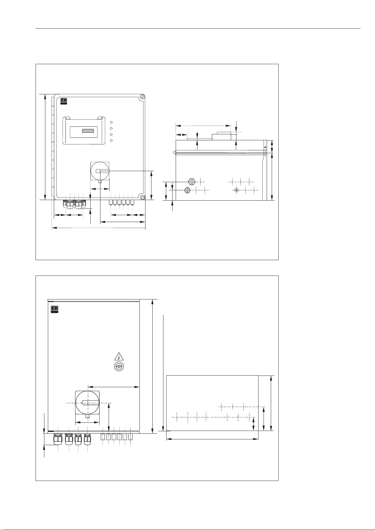
4.3 Dimensions..............................................................9
4.4 Mounting...............................................................10
4.5 Pneumatic connection. . . . . . . . . . . . . . . . . . . . . . . . . . . . . . . . . . . . . . . . . . . . . . . . . . . . . 11
4.6 Electricalconnection......................................................12
4.6.1 Safetynotes...........................................................12
4.6.2 Installation in non-Ex area . . . . . . . . . . . . . . . . . . . . . . . . . . . . . . . . . . . . . . . . . . . . . . . . 13
4.6.3 Installation in Ex area . . . . . . . . . . . . . . . . . . . . . . . . . . . . . . . . . . . . . . . . . . . . . . . . . . . . 15
4.7 Packaging and disposal . . . . . . . . . . . . . . . . . . . . . . . . . . . . . . . . . . . . . . . . . . . . . . . . . . . 17
5 Installation and start-up . . . . . . . . . . . . . . . . . . . . . . . . . . . . . . . . . . . . . . . . . . . . . . . . . . 18
5.1 Installation for version C . . . . . . . . . . . . . . . . . . . . . . . . . . . . . . . . . . . . . . . . . . . . . . . . . . . 18
5.2 Installation for non-Ex version (version M) . . . . . . . . . . . . . . . . . . . . . . . . . . . . . . . . . . . . . 18
5.3 Installation for Ex version . . . . . . . . . . . . . . . . . . . . . . . . . . . . . . . . . . . . . . . . . . . . . . . . . . 19
5.4 Start-up................................................................19
6 Operation ...............................................................20
6.1 VersionC...............................................................20
6.1.1 Operating modes . . . . . . . . . . . . . . . . . . . . . . . . . . . . . . . . . . . . . . . . . . . . . . . . . . . . . . . 20
6.1.2 External control . . . . . . . . . . . . . . . . . . . . . . . . . . . . . . . . . . . . . . . . . . . . . . . . . . . . . . . . 21
6.1.3 LEDs on CYR 20. . . . . . . . . . . . . . . . . . . . . . . . . . . . . . . . . . . . . . . . . . . . . . . . . . . . . . . . 22
6.1.4 LEDs on CPC 20-C. . . . . . . . . . . . . . . . . . . . . . . . . . . . . . . . . . . . . . . . . . . . . . . . . . . . . . 22
6.1.5 Keyfunctions..........................................................23
6.1.6 Programming . . . . . . . . . . . . . . . . . . . . . . . . . . . . . . . . . . . . . . . . . . . . . . . . . . . . . . . . . . 24
6.2 VersionM...............................................................25
6.2.1 Interval cleaning / weekly program . . . . . . . . . . . . . . . . . . . . . . . . . . . . . . . . . . . . . . . . . 25
6.2.2 Interval measurement. . . . . . . . . . . . . . . . . . . . . . . . . . . . . . . . . . . . . . . . . . . . . . . . . . . . 25
7 Maintenance and service . . . . . . . . . . . . . . . . . . . . . . . . . . . . . . . . . . . . . . . . . . . . . . . . . . 26
7.1 Error messages. . . . . . . . . . . . . . . . . . . . . . . . . . . . . . . . . . . . . . . . . . . . . . . . . . . . . . . . . . 26
7.2 Cleaning ...............................................................26
7.3 Repair .................................................................26
7.4 Accessories.............................................................26
8 Appendix ...............................................................27
8.1 Technicaldata...........................................................27
8.2 Examples for connection. . . . . . . . . . . . . . . . . . . . . . . . . . . . . . . . . . . . . . . . . . . . . . . . . . . 29
8.2.1 Non-Ex version . . . . . . . . . . . . . . . . . . . . . . . . . . . . . . . . . . . . . . . . . . . . . . . . . . . . . . . . . 29
8.2.2 Exversion.............................................................30
8.3 Index..................................................................31
0i-PC20.CHP
autoclean CPC 20 / CPC 20 Z Table of contents
Endress+Hauser 1

1 General information
1.1 Symbols used
Warning:
This symbol alerts to hazards which
may cause serious injuries as well as
damage to equipment if ignored.
Caution:
This symbol alerts to possible mal-
function due to operator error.
Note:
This symbol indicates important
items of information.
1.2 Conformity statement
The Autoclean CPC 20 / CPC 20 Z control
system has been developed and manufactu-
red in accordance with the applicable
European standards and directives.
Note:
An EC certificate of conformity may
be requested from Endress+Hauser.
An EC certificate of conformity is
supplied with variant CPC 20 Z for
installation in explosive atmospheres.
1 General information autoclean CPC 20 / CPC 20 Z
2 Endress+Hauser

2 Safety
2.1 Intended use
The Autoclean CPC 20 / CPC 20 Z control sys-
tem is used to control the automatic cleaning
of pH electrodes. It can be connected to the
retractable assemblies CPA 463, CPA 463S
or CPA 465. The Ex version CPC 20 Z permits
operation in explosive atmospheres.
2.2 General safety notes
Warning:
Operation of the device in a manner
other than as described in these
operating instructions can lead to
unsafe and improper functioning of
the measuring system.
Installation, start-up, operation
The Autoclean CPC 20 / CPC 20 Z system
has been designed for safe operation accord-
ing to the state of the art in engineering and in
keeping with the applicable regulations and
EC directives; see »Technical data«.
However, if used improperly or other than for
the intended purpose, it may pose a hazard,
e.g. due to improper connection.
Installation, electrical connection, start-up,
operation and maintenance of the measuring
system must therefore be performed exclusi-
vely by trained specialists authorised by the
system operator. This personnel must have
read and understood these operating instructi-
ons and must adhere to them.
Immunity to interference
This device is protected against interference,
such as pulse-shaped transients, high fre-
quency and electrostatic discharges, accor-
ding to the applicable European standards.
This is only valid, however, for a device con-
nected according to the notes in these instal-
lation and operating instructions.
02-PC20.CHP
autoclean CPC 20 / CPC 20-Z 2 Safety
Endress+Hauser 3

3 Description
3.1 System components
All system components are completely pre-wi-
red. The housing comes with Pg cable
glands, pneumatic connections and a vent
connection. Power, the CYR 10 injector, the
external control signals and the signal outputs
are connected to the terminal strip in the con-
trol cabinet.
The supply voltage for the non-Ex version is
230, 110 or 100 V AC or 24 V DC. All system
components are supplied with 24 V DC via
the built-in power supply unit.
The Ex version is supplied with power via the
CPM 152 measuring transmitter or via an in-
trinsically safe power supply.
Version C
The control system CPC 20-C (control via
program sequencer CYR 20) comprises:
• program sequencer CYR 20,
• pneumatic valves for assembly control,
• feedback devices (pneumatic or inductive),
• switches and keys for manual and automa-
tic operation, and
• LED operating status indicators.
Note:
The CPC 20-M / CPC 20Z-M can
only be controlled with the CPM 152
transmitter in conjunction with soft-
ware version 2.10 or later.
Version M
The control system CPC 20-M (control via
CPM 152 transmitter) comprises:
• pneumatic valves for assembly control, and
• feedback devices (pneumatic or inductive).
Version Z
The control system CPC 20 Z (control via
CPM 152 transmitter) comprises:
• pneumatic valves for assembly control, and
• feedback devices (pneumatic or inductive).
3 Description autoclean CPC 20 / CPC 20 Z
4 Endress+Hauser

3.2 Measuring system
Endress+Hauser
AUTOCLEAN CPC 20
Position SERVICE
Position MEAS
Water
Cleaner
Probfit assembly
Electr. line
Water
Cleaner Water
CYR 10
Power supply
Autoclean
CPC 20
CPM 151
(or CPM 252)
4 ... 20 mA output
Air
PC20-NX3.CDR
Compr. air
External
start/stop
External hold
Fig. 3.1
Example of a complete
measuring system in
non-Ex area
(CPC20-C)
PARAM
MEAS CAL
DIAG
Endress+Hauser
AUTOCLEAN CPC 20
Probfit assembly
Control
CPM 152
CPK 7
Electr. line
Air Cleaner
CYR 10
Water
PC20-NX2.CDR
Power supply
Compr. air
Autoclean
CPC 20
Water
4 ... 20 mA output
Control lines
Fig. 3.2
Example of a complete
measuring system in
non-Ex area
(CPC 20-M)
PARAM
MEAS CAL
DIAG
12
Probfit assembly
CPK 7
CPM 152-Z Autoclean
CPC 20 Z
Ex area Non-Ex
area
Recorder/
ext. start/stop
Compr. air
Power
supply
Water
PC20-X3.CDR
Cleaner
Electr. line
Water
Air
Injector
CYR 10Z-E12
Control line
Fig. 3.3
Example of a complete
measuring system in Ex
area (CPC 20Z)
03-PC20.CHP
autoclean CPC 20 / CPC 20-Z 3 Description
Endress+Hauser 5

3.3 Device variants
3.3.1 Nameplates
You can identify the instrument variant by the
order code on the nameplate of the instru-
ment.
Fig. 3.4 Nameplate of CPC 20
Fig. 3.5 Nameplate of CPC 20 Z
3 Description autoclean CPC 20 / CPC 20 Z
6 Endress+Hauser

3.3.2 Order code
Autoclean CPC 20
Version
C Control via program sequencer CYR 20
M Control via measuring transmitter CPM 152
Y Special version
Power supply
0 230 V, 50/60 Hz
1 110 V, 50/60 Hz
5 100 V, 50/60 Hz
824VDC
9 Special version
Feedback signals
PN For pneumatic feedback (e.g. CPA 463)
ID For inductive feedback (e.g. CPA 465)
YY Special version
Features
00 Base version
10 With compressed air monitoring (M version only)
99 Special equipment
CPC 20- ⇐complete order code
Autoclean CPC 20 Z
Version
M Control via measuring transmitter CPM 152
Feedback signals
PN For pneumatic feedback (e.g. CPA 463)
ID For inductive feedback (e.g. CPA 465)
Features
00 Base version
10 With compressed air monitoring
CPC 20 Z- ⇐complete order code
03-PC20.CHP
autoclean CPC 20 / CPC 20-Z 3 Description
Endress+Hauser 7

4 Installation
4.1 Storage and transport
The packaging material used to store or trans-
port the instrument must provide shock and
moisture protection. Optimal protection
is provided by the original packaging materi-
als. Conformance with the ambient conditions
(see »Technical data«) must be assured.
4.2 Unpacking
Verify that the contents are undamaged. In-
form the post office or freight carrier as well
as the supplier of any damage.
Check that the delivery is complete and
agrees with the shipping documents and your
order:
• Quantity delivered
• Instrument type and version according to
the nameplate (see section 3.3)
• Operating instructions
• Identification card(s)
Save the original packaging in case the de-
vice must be stored or shipped at a later time.
If you have any questions, please consult
your supplier or the Endress+Hauser sales
office in your area (see back cover of these
operating instructions for addresses).
Included in delivery:
• CPC 20-M.PN..
Switch cabinet with mounting kit
Operating Instructions
• CPC 20-M.ID..
Switch cabinet with mounting kit
Operating Instructions
Inductive proximity switches to Namur
• CPC 20-C.PN..
Switch cabinet with mounting kit
Operating Instructions
• CPC 20-C.ID..
Switch cabinet with mounting kit
Inductive proximity switches
• CPC 20Z-MPN..
Switch cabinet with mounting kit
Operating Instructions
Switch cabinet key
Ex conformity certificate
• CPC 20Z-MID..
Switch cabinet with mounting kit
Operating Instructions
Switch cabinet key
Inductive proximity switches to Namur
Ex conformity certificate
4 Installation autoclean CPC 20 / CPC 20 Z
8 Endress+Hauser

4.3 Dimensions
Cleaner
Water
Position MEAS
Position SERVICE
Endress+Hauser
AUTOCLEAN CPC 20
370
40
100
326
180
30
6
30
46
165
160
6x15 45
110
70
40
PC20Y4-3.CDR
65
~20
Fig. 4.1 Dimensions of
CPC 20
Endress+Hauser
AUTOCLEAN CPC 20 Z
65
65
135
350
150
250
PC20Y4-4.CDR
~20
38
65
Fig. 4.2 Dimensions of
CPC 20 Z
04-PC20.CHP
autoclean CPC 20 / CPC 20 Z 4 Installation
Endress+Hauser 9
Este manual sirve para los siguientes modelos
1
Tabla de contenidos
Otros manuales de Sistema de control de Endress+Hauser


