EMKO ESM-9910 Manual de usuario

ESM-9910 96 x 96 1/4 DIN Temperature Controller
- 3 D
- Selectable heating and cooling function
- Operating type selection with hysteresis
- Adjustment of temperature offset value
- Minimum pulling time adjustment for control outputs
- Password protection for programming mode
igits display
- NTC Input or,
PTC Input or,
J type thermocouple or,
K type thermocouple or,
PT-100 2-wire or 3-wire temperature input
( It must be determined in order )
- ON/OFF control form
ESM-9910 96 x 96 1/4 DIN
Digital, On/Off Temperature Controller
Instruction Manual. ENG ESM-9910 02 V07 07/14

Instruction manual of ESM-9910 temperature controller consists of three main sections.
Explanation of these sections are below. Also, there are other sections which include order
information and technical specifications of the device. All titles and page numbers in instruction
manual are in “CONTENTS” section. User can reach to any title with section number.
Installation:
In this section, physical dimensions of the device, panel mounting, electrical wiring are
explained.
Operation and Parameters:
In this section, user interface of the device, how to access to the parameters, description
of the parameters are explained.
Control Algorithm:
Configurable control function that is on the device is explained.
Also in these sections, there are warnings to prevent serious injury while doing the
physical and electrical mounting or using the device.
Explanation of the symbols which are used in these sections are given below.
This symbol is used to determine the dangerous situations as a result of an electric
shock. User must pay attention to these warnings definitely.
a
cThis symbol is used for safety warnings. User must pay attention to these
warnings.
This symbol is used to determine the important notes about functions and usage of
the device.
i
ABOUT INSTRUCTION MANUAL
2

Page 5
Page 21
Page 12
Page 7
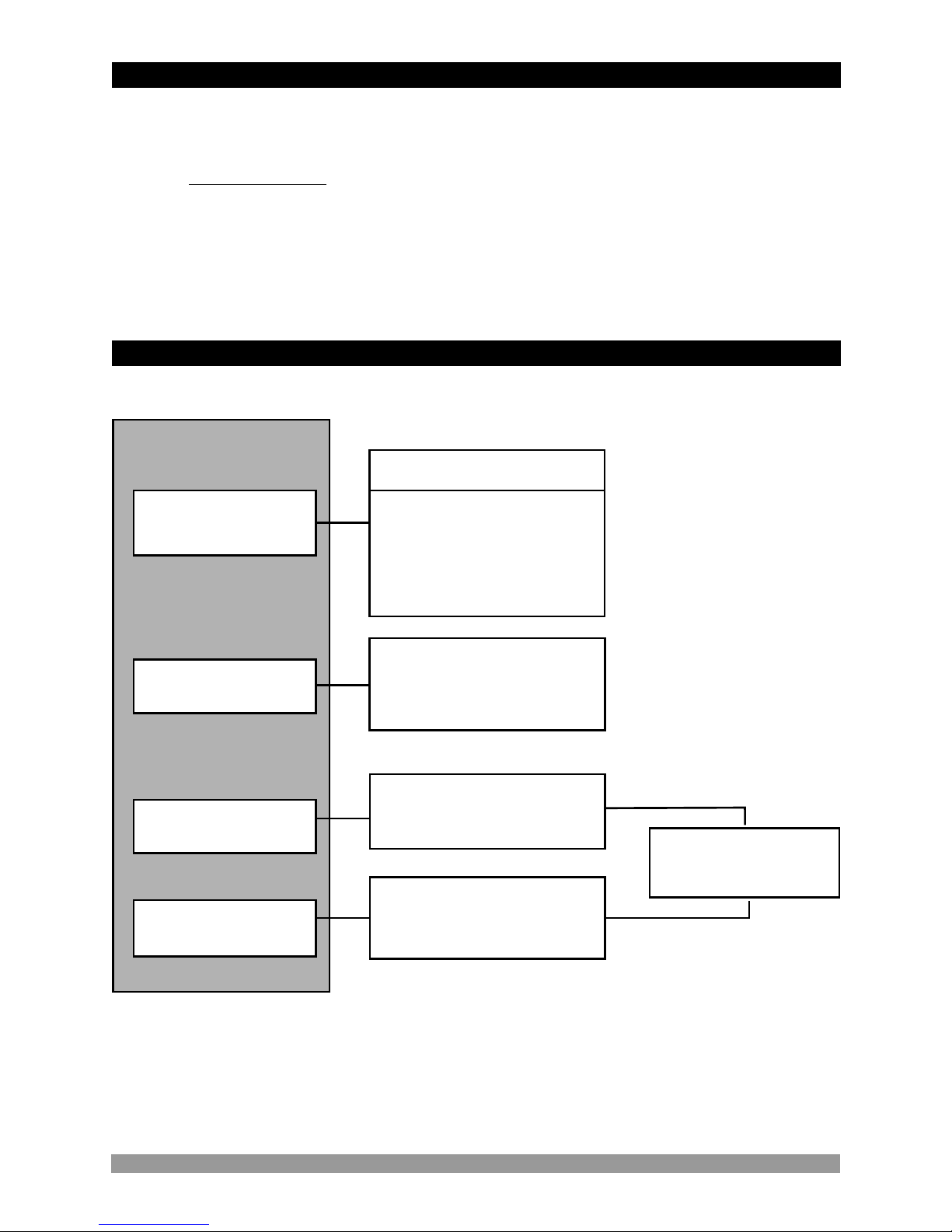
CONTENTS
1.PREFACE............................................................................................................................................
1.1 GENERAL SPECIFICATIONS
1.2 ORDERING INFORMATION
1.3 WARRANTY
1.4 MAINTENANCE
2.INSTALLATION....................................................................................................................................
2.1 GENERAL DESCRIPTION
2.2 FRONT VIEW AND DIMENSIONS OF ESM-9910 TEMPERATURE CONTROLLER WITH
ONE RELAY
2.3 FRONT VIEW AND DIMENSIONS OF ESM-9910 TEMPERATURE CONTROLLER WITH
TWO RELAYS
2.4 PANEL CUT-OUT
2.5 ENVIRONMENTAL RATINGS
2.6 PANEL MOUNTING
2.7 INSTALLATION FIXING CLAMP
2.8 REMOVING FROM THE PANEL
3.ELECTRICAL WIRINGS......................................................................................................................
3.1 TERMINAL LAYOUT AND CONNECTION INSTRUCTION
3.2 ELECTRICAL WIRING DIAGRAM
3.3 LABELS FOR ESM-9910 TEMPERATURE CONTROLLER WITH ONE RELAY
3.4 LABELS FOR ESM-9910 TEMPERATURE CONTROLLER WITH TWO RELAYS
3.5 SUPPLY VOLTAGE INPUT CONNECTION OF THE DEVICE
3.6 TEMPERATURE INPUT CONNECTION
3.6.1 TC (THERMOCOUPLE) CONNECTION
3.6.2 RTD CONNECTIONS
3.6.3 PTC AND NTC CONNECTIONS
3.7 GALVANIC ISOLATION TEST VALUES OF ESM-9910 TEMPERATURE CONTROLLER
3.8 OUTPUT-1 CONNECTIONS
3.8.1 OUTPUT-1 ( RELAY OUTPUT ) CONNECTION
3.8.2 OUTPUT-1 DRIVER OUTPUT CONNECTION
3.9 OUTPUT-2 CONNECTIONS
3.9.1 OUTPUT-2 ( RELAY OUTPUT ) CONNECTION
3.9.2 OUTPUT-2 DRIVER OUTPUT CONNECTION
4.FRONT PANEL DEFINITION AND ACCESSING TO THE MENUS....................................................
4.1 FRONT PANEL DEFINITION FOR ESM-9910 WITH ONE RELAY
4.2 FRONT PANEL DEFINITION FOR ESM-9910 WITH TWO RELAYS
4.3 OBSERVATION OF ESM-9910 TEMPERATURE CONTROLLER SOFTWARE REVISION
4.4 CHANGING AND SAVING SET VALUES
4.4.1 ESM-9910 WITH ONE RELAY
4.4.2 ESM-9910 WITH TWO RELAYS
4.5 ENTERING TO PROGRAMMING MODE, CHANGING AND SAVING PARAMETERS
4.5.1 ESM-9910 WITH ONE RELAY
4.5.2 ESM-9910 WITH TWO RELAYS
5.PARAMETERS.....................................................................................................................................
5.1 SET PARAMETERS
5.2 PROGRAM PARAMETERS
6.FAILURE MESSAGE IN ESM-9910 TEMPERATURE CONTROLLERS............................................
7.CONTROL ALGORITHM.....................................................................................................................
7.1 ON/OFF CONTROL
7.1.1 ON/OFF CONTROL IN ESM-XX10 TEMPERATURE CONTROLLERS
8.SPECIFICATIONS................................................................................................................................
9.OTHER INFORMATIONS....................................................................................................................
Page 43
Page 41
Page 45
Page 44
3
Page 46

4
Manufacturer’s Name : EMKO ELEKTRONIK A.S.
Manufacturer’s Address : DOSAB, Karanfil Sk., No:6,
16369 Bursa, TURKEY
The manufacturer hereby declares that the product:
Product Name : Temperature Controller Unit
Type Number : ESM-9910
Product Category : Electrical equipment for measurement, control and
laboratory use
Conforms to the following directives :
2006 / 95 / EC The Low Voltage Directive
2004 / 108 / EC The Electromagnetic Compatibility Directive
has been designed and manufactured to the following specifications:
EN 61000-6-4:2007 EMC Generic Emission Standard for Industrial Environments
EN 61000-6-2:2005 EMC Generic Immunity Standard for Industrial Environments
EN 61010-1:2001 Safety Requirements for electrical equipment for measurement, control
and laboratory use
When and Where Issued Authorized Signature
th
16 October 2009 Name : Serpil YAKIN
Bursa-TURKEY Position : Quality Manager
EU DECLARATION OF CONFORMITY
1.1 General Specifications
ESM-9910
Standard
Output-2 (Relay
Output)
Output-1 (Relay
Output)
1.Preface
ESM series temperature controllers are designed for measuring and controlling
temperature. They can be used in many applications with On/Off control form and heating and
cooling selection. Some application fields which they are used are listed below:
Application Fields
Glass
Plastic
Petro-Chemistry
Textile
Automative
Machine Production Industries
Optional (Note-1)
Note-1: Optional Relay output is standard in ESM-9910 with two relays
Temperature Sensor
Input
Supply Voltage
Input
Control Output
Alarm Output
Control Output
Alarm Output
Heating or Cooling
Function
ON/OFF Operation
5
Standard
230 V V (±%15) , 50/60 Hz
Optional Supply Voltage
Inputs
115 V V (±%15) , 50/60 Hz
24 V V (±%15) , 50/60 Hz
NTC
PTC
J or K Type TC
2 or 3 wire PT 100
24 V W ( - %15, + %10 )
50/60 Hz

1.2 Ordering Information
c
1.3 Warranty
EMKO Elektronik warrants that the equipment delivered is free from defects in material and
workmanship. This warranty is provided for a period of two years. The warranty period starts from
the delivery date. This warranty is in force if duty and responsibilities which are determined in
warranty document and instruction manual performs by the customer completely.
1.4 Maintenance
Repairs should only be performed by trained and specialized personnel. Cut power to the device
before accessing internal parts.
Do not clean the case with hydrocarbon-based solvents (Petrol, Trichlorethylene etc.). Use of
these solvents can reduce the mechanical reliability of the device. Use a cloth dampened in ethyl
alcohol or water to clean the external plastic case.
All order information of ESM-9910
Temperature Controller are given on the
table at left. User may form appropriate
device configuration from information and
codes that at the table and convert it to the
ordering codes.
Firstly, supply voltage then other
specifications must be determined. Please
fill the order code blanks according to your
needs.
Please contact us, if your needs are
out of the standards.
V Þ Vac,
Z Þ Vdc,
Þ VacdcW
6
ESM-9910 (96x96 1/4 DIN )
A BC D E FG HI /
/
U V W Z/
/0 00 2 0 0
12
05
09
J ,Fe CuNi IEC584.1(ITS90)
PTC (Note-1)
Input Type
BC Scale(°C)
-50°C 150°C
0°C 800°C
-19.9°C 99.9°C
PT 100 , IEC751(ITS90)
10 K ,NiCr Ni IEC584.1(ITS90)
400°C
0°C 999°C
PT 100 , IEC751(ITS90) 0°C
PTC (Note-1)
15 -19.9°C 99.9°C
03
Temp.Sensor which is given with ESM-9910
V
0None
1PTC-M6L40.K1.5(PTC Air probe with 1.5 m silicon cable)
2PTCS-M6L30.K1.5.1/8”(PTC Liquid probe with 1.5 m silicon cable)
19 -19.9°C 99.9°C
-50°C 100°C
18
NTC (Note-1)
NTC (Note-1)
Note-1 : If input type is selected PTC or NTC (BC = 12, 15, 18, 19 ),
Temperature sensor is given with the device. For this reason,
If input type is selected as PTC, sensor type (V = 0, 1 or 2) or
If input type is selected as NTC, sensor type (V = 0, 3 or 4) must be
declared in ordering information.
Customer
3NTC-M5L20.K1.5 (NTC Probe, thermoplastic moulded with
1.5 m cable for cooling application)
4NTC-M6L50.K1.5 (NTC Probe, stainless steel housing with
1.5 m cable for cooling application)
9
1 Relay Output(7A@250VVat resistive load,1NO+1NC)
00
Output-1
E
Output-2 FG
None
01 Relay Output(7A@250VVat resistive load,1NO+1NC)
Supply Voltage
24 V V ( ± %15 ) 50/60 Hz
A
3
Customer
9
115 V V ( ± %15 ) 50/60 Hz
4
230 V V ( ± %15 ) 50/60 Hz
5
224 V W ( - %15, + %10 ) 50/60 Hz
2SSR Driver Output (Maximum 23mA,15V)
02 SSR Driver Output (Maximum 23mA,15V)

In package ,
- One piece unit
- Two pieces mounting clamps
- One piece instruction manual
A visual inspection of this product for possible damage occured during shipment is
recommended before installation. It is your responsibility to ensure that qualified
mechanical and electrical technicians install this product.
If there is danger of serious accident resulting from a failure or defect in this unit, power
off the system and separate the electrical connection of the device from the system.
The unit is normally supplied without a power switch or a fuse. Use power switch and fuse
as required.
Be sure to use the rated power supply voltage to protect the unit against damage and to
prevent failure.
Keep the power off until all of the wiring is completed so that electric shock and trouble
with the unit can be prevented.
Never attempt to disassemble, modify or repair this unit. Tampering with the unit may
results in malfunction, electric shock or fire.
Do not use the unit in combustible or explosive gaseous atmospheres.
During the equipment is putted in hole on the metal panel while mechanical installation
some metal burrs can cause injury on hands, you must be careful.
Montage of the product on a system must be done with it’s own fixing clamps. Do not do
the montage of the device with inappropriate fixing clamp. Be sure that device will not fall
while doing the montage.
It is your responsibility if this equipment is used in a manner not specified in this
instruction manual.
Before beginning installation of this product, please read the instruction
manual and warnings below carefully.
2.Installation
c
7

2.1 General Description
2.2 Front View and Dimensions of ESM-9910 Temperature Controller with One Relay
S9
EM 0
91
-
Panel surface
(maximum thickness 15 mm / 0.59 inch)
96 mm / 3.78 inch
96 mm / 3.78 inch
M-
S 910
9
E
ET
S
ET
S
UT
ORO
PG
P
Front Panel
IP65 protection
NEMA 4X
Mounting Clamp
12 ± 1 mm / 0.47 inch 84 mm / 3.31 inch
Maximum 15 mm / 0.59 inch
8

2.4 Panel Cut-Out
129 mm/5,08 inch (min)
129 mm/5,08 inch (min)
92 mm / 3.62 inch
92 mm / 3.62 inch
96 mm / 3.78 inch
96 mm / 3.78 inch
M-10
S99
E
2.3 Front View and Dimensions of ESM-9910 Temperature Controller with Two Relays
12 ± 1 mm / 0.47 inch 84 mm / 3.31 inch
Maximum 15 mm / 0.59 inch
9

1
2
3
91
S0
E-
M9
c
Operating Temperature : 0 to 50 °C
Max. Operating Humidity : 90% Rh (non-condensing)
Altitude : Up to 2000 m.
Operating Conditions
Forbidden Conditions:
Corrosive atmosphere
Explosive atmosphere
Home applications (The unit is only for industrial applications)
2.5 Environmental Ratings
2.6 Panel Mounting
c
During installation into a metal panel, care should be taken to avoid injury from
metal burrs which might be present. The equipment can loosen from vibration
and become dislodged if installation parts are not properly tightened. These
precautions for the safety of the person who does the panel mounting.
1-Before mounting the device in your
panel, make sure that the cut-out is of
the right size.
2-Check front panel gasket position
3-Insert the device through the cut-
out. If the mounting clamps are on the
unit, put out them before inserting the
unit to the panel.
10
Tabla de contenidos
Otros manuales de Controladores de temperatura de EMKO

EMKO
EMKO ESM-9910.5.12.0.1/01.00/2.0.0.0 Manual de usuario

EMKO
EMKO ESM-1510-N Manual de usuario

EMKO
EMKO ESM-4420 Manual de usuario

EMKO
EMKO ESM-3710-N Manual de usuario

EMKO
EMKO ESM Series Manual de usuario

EMKO
EMKO ESM-7710 Manual de usuario

EMKO
EMKO ESM-3710-N Manual de usuario

EMKO
EMKO ESM-3711-H Manual de usuario

EMKO
EMKO ESM-3712-HC Manual de usuario

EMKO
EMKO ESM-3723 Manual de usuario


