Emerson GO USB Logger Manual de usuario

GO USB Loggers
User Manual
Cargo Monitoring Solutions

2
Table of Contents
Page
Introduction 3
Understanding the Device 3-4
Display Information 5
Battery Installation 6
Operating Instructions 6-7
GO USB Probe (TP1XD Model) Custom Instructions 8
File Names and Extensions 9
Understanding the PDF Data File 9-12
Conguration Software 13
Using the Software 13-15
Troubleshooting and FAQ's 16-17
Technical Support 18

3
The family of GO USB Loggers are congurable temperature and humidity devices for your
cold chain needs.
An accompanying conguration software allows users to customize the logger to meet specic
customer requirements. Data gathered and stored is easily accessible via a secure PDF le and
available to share with key stakeholders. Time stamp recordings at the end of the PDF document
create an audit trail of logger events.
Introduction
Understanding the Device
LED light
(Green = On, Red = Alert)
USB connector cover
GO USB Humidity (TH1XD)
Humidity venting hole
Start/Stop
Hang strap connector (side)
Operating Instructions (back side)
Battery compartment (back side)
Probe jack
(only for TP1XD)
LCD Display
(Navigation buttons)
Serial number
(bottom side)
Loggers come pre-congured from the
factory with the following settings:
• Alerts: None
• Recording interval: 5-minutes
• Memory mode: Stop when full
What’s in the box
• Five GO USB Loggers
• Five ER14250 (1/2 AA) Lithium batteries
• Five hang straps
• Only TP1XD model: Five dry ice probes
• Only TP1XD model: One calibration certicate

4
USB connector cover
GO USB Temperature (T1XD)
Start/Stop
Hang strap connector (side)
Operating Instructions (back side)
Battery compartment (back side)
Probe jack
(only for TP1XD)
LCD Display
(Navigation buttons)
Serial number
(bottom side)
Understanding the Device
USB connector cover
GO USB Probe (TP1XD)
Start/Stop
Hang strap connector (side)
Operating Instructions (back side)
Battery compartment (back side)
Probe jack
(only for TP1XD)
LCD Display
(Navigation buttons)
Serial number
(bottom side)
LED light
(Green = On, Red = Alert)
LED light
(Green = On, Red = Alert)

5
The following icons are available and
can be navigated by clicking the Start
or Stop buttons.
Display Information
C: Temperature, Humidity (TH1XD)
and Probe (TP1XD).
Hourglass: When logger is in
“start delay mode” or
synchronizing with PC
Max: Maximum ambient temperature
and humidity (TH1XD), ambient temperature (T1XD), or ambient temperature and probe
temperature (TP1XD) during the recording period.
Min: Minimum ambient temperature and humidity (TH1XD), ambient temperature (T1XD), or
ambient temperature and probe temperature (TP1XD) during the recording period.
AVG: Average ambient temperature and humidity (TH1XD), ambient temperature (T1XD), or
ambient temperature and probe temperature (TP1XD) during the recording period.
MKT: Mean Kinetic ambient temperature the logger and probe (TP1XD), has experienced during the
recording period.
I: Current interval setting.
P: Current probe temperature value (TP1XD only).
°C: If logger is congured to display Celsius.
°F: If logger is congured to display Fahrenheit.
%: Relative humidity percentage (TH1XD only).
Battery Status: Estimated battery life remaining.
REC: Indicates logger is actively recording data.
Clock: Current or running time as congured by the software.
Bell: Alert for temperature and/or humidity excursion (only applicable model).
Q: Quantity of measurements captured.

6
Note: Once battery is depleted, it cannot be recharged and should be properly discarded according
to local recycling guidelines. It is recommended that replacement batteries be the same make and
model. Should you replace1 the battery with a different ER14250 battery model, please review the
manufacturer’s safety documentation and certications such as:
The GO USB Loggers come with pre-installed, non-rechargeable ER14250 ½ AA batteries. Ensure
battery compartment is securely in place prior to use.
• Material Safety Datasheet
• UN 38.3 report
• Other certications as applicable
Battery Installation
1Screwdriver not included
To start recording, press and hold Start for ~3 seconds and then release. A green LED will ash
and a REC symbol will appear on the LCD to indicate successful activation. The LED light will ash
intermittently to indicate active recording. In the event of an alert, the LED will ash a red color. The
unit can be congured to alert with sound. You may disable the sound by pressing and holding the
STOP button for ~0.5 seconds. To stop recording, press and hold Stop for ~3 seconds and release.
The REC symbol will disappear to indicate successful deactivation. The LED light will no longer blink
intermittently.
Operating Instructions
Note: To prevent accidental deactivation, the conguration software has an option to disable
the stop button. In the event the logger does not stop recording when pressing the stop button
for 3 seconds, it is likely this feature has been enabled. Reconnect the logger to a PC and use the
conguration software to stop the logger. See the Conguration Software section for more detail.

7
The GO USB Loggers are designed to continue recording data until manually stopped or until memory
is full unless the FIFO (rst-in, rst-out) mode is enabled. When connected to a PC, the logger will
continue recording temperature information. If the logger has not been manually stopped (either
via button or software) an INTERIM.pdf and INTERIM.csv le will be available in the directory. This le
name indicates recording is ongoing. You may transfer the le(s) to your PC and rename manually.
Once stopped, the logger will rename the PDF and CSV le with the serial number of the logger. You
may connect to PC to download the generated reports (PDF and/or CSV) at any time. To ensure data
integrity, the PDF report cannot be manually deleted from the logger root directory. If an attempt to
delete the PDF or CSV le is made, reports will auto generate next time the logger is connected to a
PC.
To cycle through the LCD information, click (short press) either the Start or Stop button. Navigation
arrows indicates direction of information.
You may wish to create “Marked events” on your PDF and CSV report to indicate an event or
occurrence. To create a marked event, simultaneously press and hold the Start+Stop button for ~2
seconds. The green LED will blink rapidly to indicate successful marking.
Operating Instructions (cont’d)
If you wish to clear the memory of the device and to start a new recording, you can either utilize the
conguration software (see conguration software section) or to stop the logger and manually start
it again. This action will clear memory and start a new data set.
The hang strap which accompanies the logger can be used to hang the logger at a location within the
shipment. If this strap is not needed, it may be removed.

8
The TP1XD logger has been shipped with a pre-calibrated probe. Prior to using the probe, ensure that
the probe serial number matches the serial number of the logger. The serial number is found on the
ag sticker of the probe. The serial number of the USB logger is found at the bottom of the logger.
Please note: Failing to match the probe to the correct logger will not prevent
use of probe but may have an adverse effect on calibration accuracy.
GO USB Probe (TP1XD Model) Custom Instructions
9
File Names and Extensions
The USB Loggers generate two (2) le types after connecting to the PC.
• A secure PDF2 le that can be transferred to the PC and shared at any time.
• A CSV le which can be transferred to the PC and shared at any time.
2For data integrity and security reasons, it is recommended to only share PDF les.
Understanding the PDF Data File
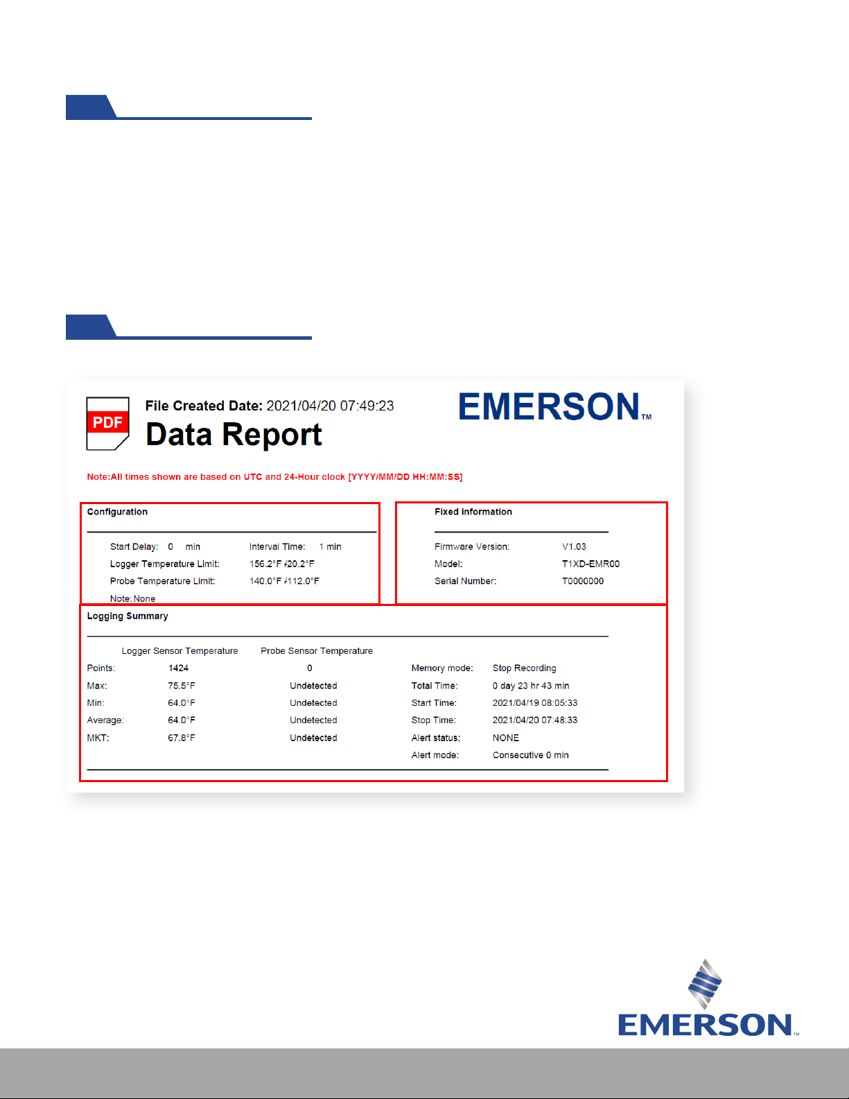
Once connected to your PC via USB, a data report similar to the one below is created:
1. The conguration section of the PDF report refers to the temperature and
humidity limits and recording interval congured via the conguration software.
2. Fixed information refers to rmware version, model, and serial number.
This information is xed and cannot be altered via software.
3. Logging summary refers to data collected up to the point of PDF le being
generated. Triggered alerts and alert mode are visible here.
1 2
3
TP1XD summary report example.
10
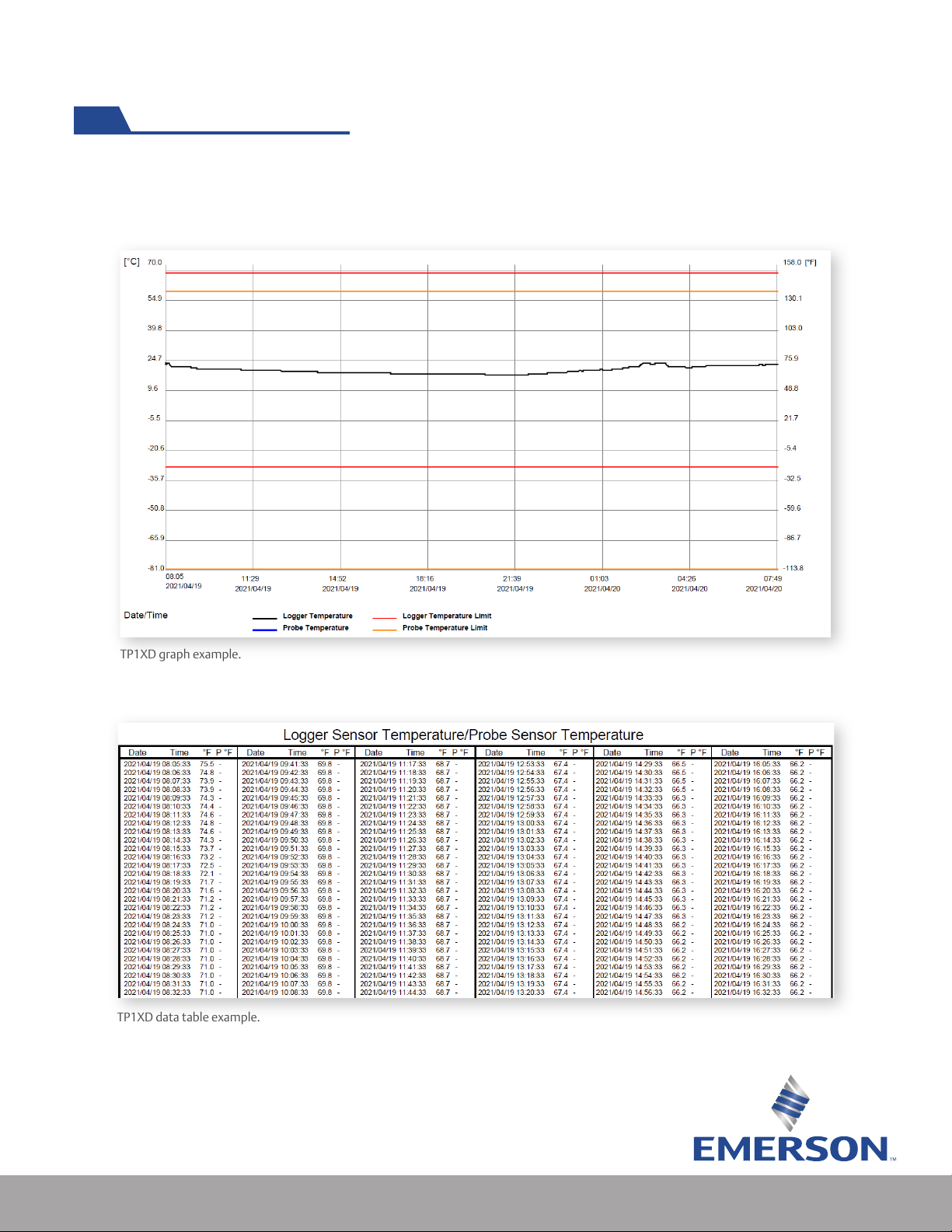
Every PDF report comes with a historical record in a graph and table form. If alert thresholds have been
congured, they are displayed and color coded. A legend can be found below the graph as a reference.
TP1XD graph example.
Each consecutive page following the graph contains the time and measurement point collected.
TP1XD data table example.
Understanding the PDF Data File (cont’d)
Este manual sirve para los siguientes modelos
6
Tabla de contenidos
Otros manuales de Registrador de datos de Emerson


