EmerCom Technologies LAN-EX Series Manual de usuario

Ethernet LAN Extender
USER GUIDE
LAN-EX
for an Elevator Media Player
LAN-EX User Guide
- 2 -
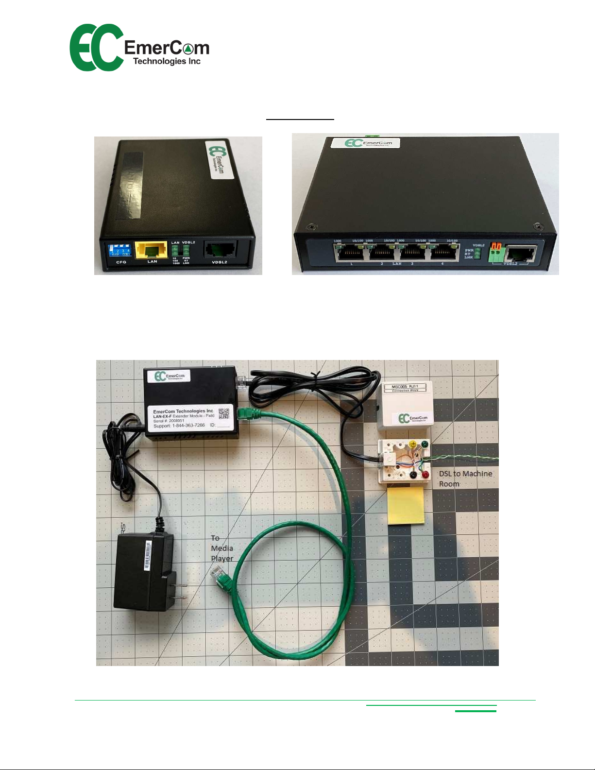
Other Models
LAN-EX-G LAN-EX-4G
LAN-EX-F (Elevator Cab Kit)

LAN-EX User Guide
- 3 -
LAN-EX-H (Typical Elevator Machine oom Panel/Kit)
Connect 120VAC power
in conduit
Connect STP from cab
Ground shield
Connect CAT- from
Server
Ground shield

LAN-EX User Guide
- 4 -
uick Start Guide
Customer Care: Call 1-844-EMERCOM (1-844-3 3-72 ) for assistance.
Connect Machine Room wiring:
VDSL terminals in Machine Room
Panel to STP in Controller from
traveling cable (match correct cab
number)
CAT-5e or CAT- Cable to Media
Server from Machine Room Panel
Switch
1
Connect cab wiring:
Cab LAN CAT-5e Patch Cable to
Media Player
Cab VDSL to STP in traveling cable
via Connection Block
Power (PWR IN)
Power-up:
Apply Power to all equipment between the
Server and the Media Screen and after a
minute or two, the LNK LEDs will “flicker”
indicating data flow when the link is
established.
Verify the Ethernet connection.
2
3

LAN-EX User Guide
- 5 -
Copyright © 2020 by EmerCom Technologies Inc
LAN-EX User Guide
ALL RIGHTS RESERVED
NOTICE
The information in this document has been carefully checked and is believed to be accurate. However,
no responsibility is assumed or implied for inaccuracies. Furthermore, EmerCom Technologies Inc
reserves the right to make changes to any products herein described to improve reliability, function or
design. EmerCom Technologies Inc does not assume liability arising from the application or use of any
product or circuit described herein; neither does it convey any license under its patent rights nor the
rights of others.
This manual and all data contained constitute proprietary information of EmerCom Technologies Inc and
shall not be reproduced, copied or disclosed to others, or used as the basis for manufacture without
written consent of EmerCom Technologies Inc.

LAN-EX User Guide
- -
Contents
1. About the EMC-LAN-EX LAN Extender ........................................................................................... 7
1.1 Description............................................................................................................................... 7
1.2 Key Features ............................................................................................................................ 7
2. Description of Operation: ............................................................................................................. 8
3. Circuit Board Layout & Connections.............................................................................................. 9
3.1 Front Panel .............................................................................................................................. 9
3.2 LED activity if operating correctly: ............................................................................................ 9
3.3 The LAN status LEDs indicate: ................................................................................................. 10
3.4 The VDSL status LEDs indicate: ............................................................................................... 10
3.5 Connections ........................................................................................................................... 11
3. Connector Pin-Outs ................................................................................................................ 12
4. Diagnostics ................................................................................................................................. 13
5. Dimensions................................................................................................................................. 13
. Ordering ..................................................................................................................................... 13
7. Precautions ................................................................................................................................ 14
8. Warranty .................................................................................................................................... 15

LAN-EX User Guide
- 7 -
1. About the EMC-LAN-EX LAN Extender
1.1 Description
The LAN-EX transmits high-speed Ethernet over long distances on STP (Shielded
Twisted Pair) which is particularly relevant for elevator hoistways which are electrically
“noisy” (both electrostatic and electromagnetic) compared to standard LAN Extenders
requiring unshielded wiring which would be significantly more susceptible to noise.
The basic LAN-EX modem operates in pairs in bridge mode, each with one J45
Ethernet port and one J45 (2-wire) VDSL port transmitting up to 100Mbps of
symmetric data over copper wires. Symmetrical or asymmetrical transmission can be
selected with bandwidth up to 100/100 Mbps (line rate) within 1,000’ (~300m) or
10/10 Mbps for 3,000’ (~900m) connections. Gbps models are available wherever more
bandwidth is required.
One-way or even two-way video streaming and telephone voice can be multiplexed to
share the same pair of wires although, if available, separate pairs reduce
troubleshooting complications.
In summary the LAN-EX provides a reliable, cost-effective method to deliver Ethernet to
an elevator over standard traveling cable shielded twisted pairs.
1.2 Key Features
Cost-effective long-distance Ethernet bridge
Asymmetric mode provides the highest line rate with directional control via DIP
switch
Symmetric mode provides up and down transmission as would be required for a
camera and a media player
Supports “flow control” with Pause Frame or Back Pressure
Selectable profiles are available for maximum data rate to suit different
requirements, for example less error checking and high or lower signal to noise
ratio (SN ).
19-inch rack mountable (2U)
Ease of setup and operation
LEDs for diagnostics

LAN-EX User Guide
- 8 -
2. Description of Operation:
Select the settings on the DIP switches to suit the operation required:
Asynchronous for media player only (faster in one direction)
Synchronous for media player and camera
Select the profile (DSL mode) for the highest data rate or longest distance
Select the SN (Signal:Noise) to suit the application
and turn on the power.
The modules will connect and LEDs illuminate according to the settings. The
LNK (link) LEDs will start slow on-off then begin to flicker fast to indicate data flow.

LAN-EX User Guide
- 9 -
3. Circuit Board Layout & Connections
3.1 Front Panel
Front panel can be separated into five parts from left to right:
DIP switch (head-end or field/profile/uni- or bi-directional/signal:noise)
J45 connector for Ethernet (LAN)
LEDs for LAN (left-hand column)
LEDs for VDSL (Very high-speed Digital Subscriber Line)
J45 connector for single pair VDSL
The DIP Switch selects:
Pin 1 Pin 2 Pin 3 Pin 4
Head/Field Profile Direction SNR
Off OT (Head) High throughput
Symmetric 9dB
On T (Field) Long each Asymmetric 6dB
3.2 LED activity if operating correctly:
Head End Field
Blinking fast

LAN-EX User Guide
- 10 -
3.3 The LAN status LEDs indicate:
LEDs for
LAN
Blinking
On
Off
Data activity Linked Not linked
-
100 Mbps 10 Mbps
-
Full Duplex Half Duplex
3.4 The VDSL status LEDs indicate:
LEDs for
VDSL
Blinking
On
Off
-
Power ON Power NOT ON
-
Field Head End
Slow – Idle
Pulsing – Linking
Very fast – Data flowing
Should flash Off line
Este manual sirve para los siguientes modelos
4
Tabla de contenidos


