10 Elsys AGSGA2 User Guide
4.3 Software Settings
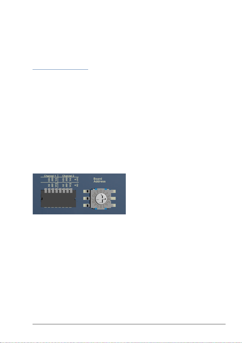
All hardware settings that are set via the
DIP switches can also be configured via the
software. As soon as a setting has been made
via the software, the DIP switch settings are
ignored.
To return to the hardware settings, the cor-
responding reset command must be sent via
software or the reset button on the front panel
must be pressed for at least 3 seconds.
When the software is started, all COM ports
are scanned for a connected amplifier. If an
amplifier is found, the connection is estab-
lished automatically.
Bridge Configuration
• For 6-wire measurements, enable “Use
Voltage Sense”
• Configure the amplifier as Full-Bridge or as
Half/Quarter bridge.
• If Quarter bridge is used, the internal resis-
tor R4 must be mounted.
Auto-Oset / Zero
Before the measuring bridge can be used, it
must be balanced, otherwise an oset voltage
is measured which can overdrive the amplifier.
To a certain extent, the amplifier can compen-
sate for the oset. To do this, press the “Zero”
button on the front panel or click on “Auto
Oset” in the software. The LEDs on the front
indicate whether the oset compensation was
successful.
Front LEDs
There is a two-colour LED (red and green) for
each channel.
Color Description
O Output signal outside ± 100mV
Green Output signal within ± 100mV
Red Error during Zero compensation
Orange Error during Zero compensation, currently
gain settings within ± 100mV
Live Values
The Check box “Enable live value” returns the
measured voltage of the selected channel
according to its configuration. Please note that
the live value or the software command
GETADC returned value has a precision of
approx. 2% and is meant to see a trend or
position of a sensor or measurement. For high
speed and high resolution, the signal must be
measured on the analog output with a dedicat-
ed Transient Recorder.