IOMOD 16DI is small sized stand-alone Modbus (RTU) or IEC 60870-5-103 digital input controller. IOMOD is used for
industrial applications, where digital signaling is used and robust communication is needed. IOMOD is ideal solution for
applications such as data acquisition, observation, process monitoring, testing and measurement at remote places. It
is controlled over Modbus or IEC 60870-5-103 protocol, and can be used with any SCADA system.
16 digital inputs with configurable active signal polarity, or input inversion; Pulse count and ON time count
Galvanically isolated inputs
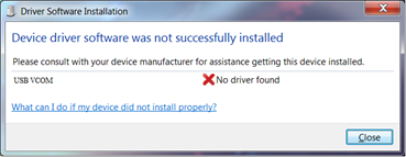
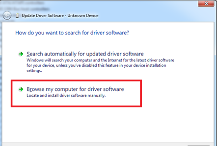
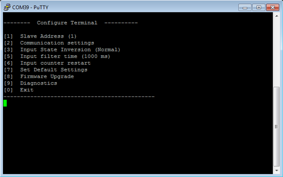
Configurable over USB
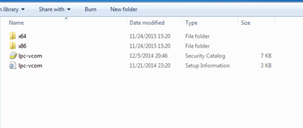
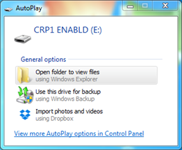
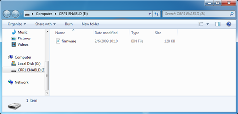
Drag And Drop firmware upgrade over USB
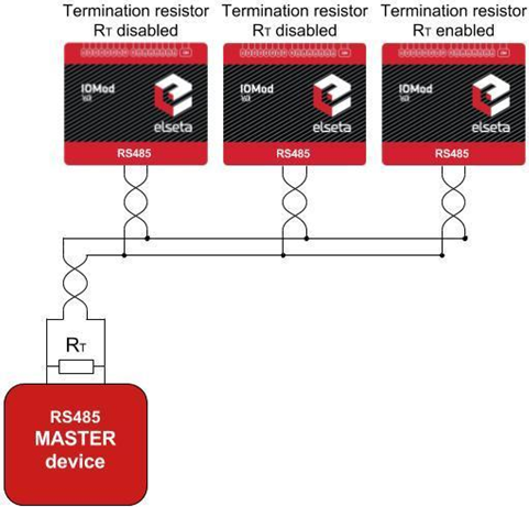
RS485 communication
LED input indications, + Data transmission (Rx and Tx) indication.
Small sized case with removable front panel
DIN rail mount
Operating temperature: from -30 to +70°C
Power Requirements: 12-24 VDC
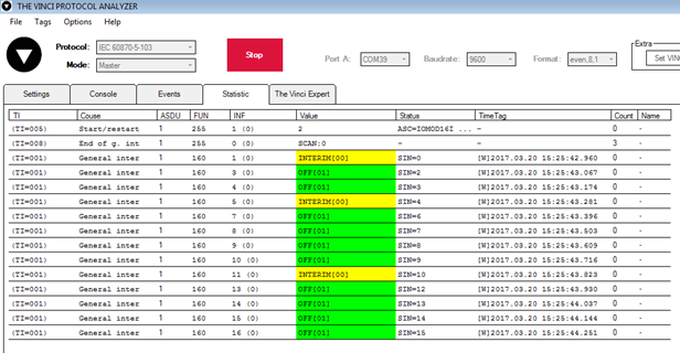
IOMOD 16DI uses Modbus (RTU) or IEC 60870-5-103 protocol over RS485 interface. Protocol used by device can be
changed by uploading corresponding firmware. Default communication settings are: 9600 baudrate, 8N1, Slave
address - 1.
To read all input statuses, send 02 Modbus command (Read Discrete Inputs) 03 Modbus command with resolution of
first register (0) and a size of 16. Returned value will show 16 input states.
To read all input registers’ values, send 04 Modbus command (Read input registers) with resolution of first register (0)
and size of 80. Returned data will show pulse count (first register) and ON time (2nd and 3rd registers) for each input –
pulse count of input #2 will be at register 4th, and so on. ON time will be shown as seconds. ON time and pulse count
will increase when input pulse is longer than Filter time, which is configured by user in USB terminal menu. Shorter
pulses will be ignored in both pulse and ON time registers. From software version 1.10, as capacity of input counter
expanded to 32-bits, additional 32 registers depict such wider values in registers 00048-00079. All these registers can
be set by using 06 Modbus command.
To invert input states by software, configure device over USB terminal. Modbus commands one may use are shown in
table below.
02 (0x02) Read Discrete Inputs
Reads status of digital inputs (Off or On). IOMOD 16DI has 16 digital inputs from address 0 to address 0xF; These
inputs are active-high or active-low according to supply given to reference input. User can turn on logical input
inversion (through USB).
03 (0x03) Read Holding Registers
Lets user read counter/timer values dedicated to digital inputs. There are 80 MODBUS registers. Values held in these
registers are explained in a table below. There are two types of values - Pulse Counter and On Timer, the latter
calculating the time that respective input was held in its active state.
04 (0x04) Read Input Registers
Lets user read counter/timer values dedicated to digital inputs. There are 80 MODBUS registers. Values held in these
registers are explained in a table below. There are two types of values - Pulse Counter and On Timer, the latter
calculating the time in seconds that respective input was held in its active state. This function is deprecated and
mirrors function 0x03 to conform to past versions of IOMOD 16DI.
06 (0x06) Preset Single Register
Sets single register. Register addresses are identical to
“Read Input Registers”
addresses.
IOMOD 16DI User Manual Modbus
Introduction
Features
Device operational information
MODBUS operational information
Supported MODBUS functions
Modbus register mapping table


