V1.1 | ELSETA | Operational information
On first Class 1 request IOmod device always asks for the Access Demand to send an identification
string. However, if there are spontaneous messages to be sent, they will be sent before the identification
string.
2.1.3 Output control
To control device outputs master (controlling station) sends command conforming to the IEC-60870-5-
103 protocols. It should contain output address which is 128 by default. Info number represents number
of output pin, while info elements shows DPI information of output state (1 – off, 2 – on, 0 - intermediate
and 3 – not used (defines error)). Successful command is accepted with a positive acknowledge.
Negative acknowledge is returned if the output is already set or if another command for the same output
is already in progress and hasn’t finished yet.
2.1.4 Input messages
When input status changes, IOmod device filters input glitches through filters with a user configurable
filter time. When the filter is passed device sends “Spontaneous” message with “Function type” as input
address (default function type of inputs – 160), and “Info number” as input pin number. Please note that
spontaneous messages are answered with a four-byte time structure not containing date info. Controlling
station should therefore be able to handle the signals sent before the start of a new day.
2.1.5 Time synchronization
To initiate the time synchronization between devices master must send variable frame, with function code
“User data with ACK”, ASDU type “6” and Cause of Transmission “8”. Info elements must contain the 7-
byte time structure.
As per IEC-60870-5-103 protocol specification time synchronization can be completed for multiple
devices using broadcasting messages. It is included in IEC-60870-5-103 firmware since version 1.7.3.
To broadcast time synchronization message, link address should be equal to 255.
2.1.6 General interrogation
General Interrogation (GI) is initiated by the master with variable frame, including function code “3” (User
data with ACK), ASDU type “7” and Cause of Transmission “9”. Slave device then responds with an
acknowledgement (ACK). Master gets GI data by polling with Class 2 request till slave transmits “End of
GI” (Cause of Transmission – “10”). IOmod device responds with a time-tagged message, including DPI
states of inputs and outputs (Outputs are sent first). Output and input numbers are represented by “Info
number” in protocol.
2.2 DEVICE CONFIGURATION
2.2.1 Input inversion and polarity selection
When active low signalling is needed, user can configure input polarity. When internal pull-up resistors
are turned on, all input statuses are turned on. When low signal is connected to input, status of that input
is turned off. If user desires to turn input status on, when that input signal is low, user then inverts inputs
logically. All input indication LED’s stay the same (are not inverted).
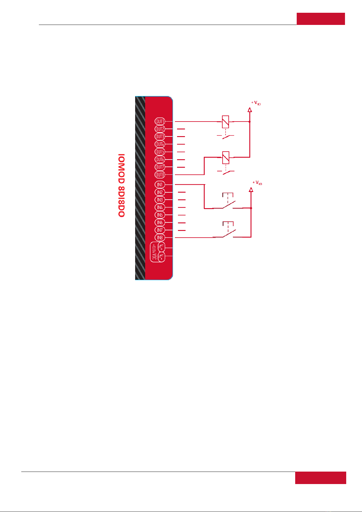
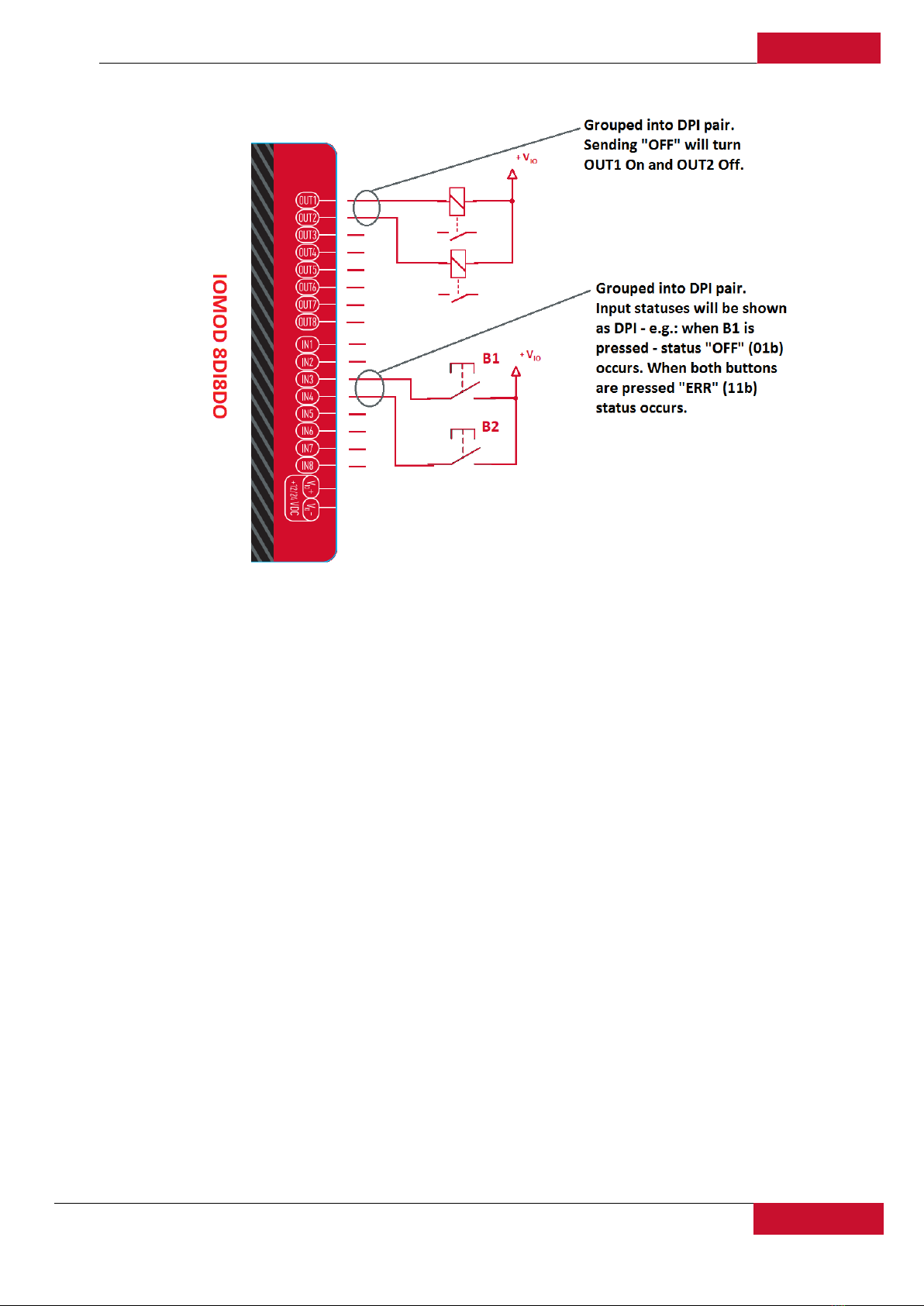
2.2.2 Input / Output grouping
Sometimes two inputs or two outputs must be captured as one DPI input or output. Inputs and outputs
can be grouped into the pairs of two. This allows outputs to be controlled by one DPI command (of
address of first output in the group). Only two neighbour pins can be grouped into pair, while first pin in
pair must be an odd number pin. When grouped, second pin in the pair is not used anymore – all requests
for this pin generate an error. For example – OUT1 and OUT2 can be grouped, after that OUT2 is not