Elmo ET4 Manual del propietario

Microprocessor-based control units with
remote assistance function
ET4
USER AND PROGRAMMING MANUAL

2 - ET4 - USER AND PROGRAMMING MANUAL
FOREWORD
FOR THE INSTALLER:
Please follow carefully the specifications relative to electric and security systems realization further to the manufac-
turer’s prescriptions indicated in the manual provided.
Provide the user the necessary indication for use and system’s limitations, specifying that there exist precise
specifications and different safety performances levels that should be proportioned to the user needs. Have the user
view the directions indicated in this document.
FOR THE USER:
Periodically check carefully the system functionality making sure all enabling and disabling operations were made cor-
rectly.
Have skilled personnel make the periodic system’s maintenance. Contact the installer to verify correct system oper-
ation in case its conditions have changed (e.g.: variations in the areas to protect due to extension, change of the ac-
cess modes, etc…)
......................................................
This device has been projected, assembled and tested with the maximum care, adopting control procedures in
accordance with the laws in force. The full correspondence to the functional characteristics is given exclusively when
it is used for the purpose it was projected for, which is as follows:
Microprocessor-based control units with remote assistance function
Any use other than the one mentioned above has not been forecasted and therefore it is not possible to guarantee
its correct operativeness.
The manufacturing process is carefully controlled in order to prevent defaults and bad functioning. Nevertheless, an
extremely low percentage of the components used is subjected to faults just as any other electronic or mechanic prod-
uct. As this item is meant to protect both property and people, we invite the user to proportion the level of protection
that the system offers to the actual risk (also taking into account the possibility that the system was operated in a de-
graded manner because of faults and the like), as well reminding that there are precise laws for the design and as-
semblage of the systems destinated to these kind of applications.
The system’s operator is hereby advised to see regularly to the periodic maintenance of the system, at least
in accordance with the provisions of current legislation, as well as to carry out checks on the correct running
of said system on as regular a basis as the risk involved requires, with particular reference to the control unit,
sensors, sounders, dialler(s) and any other device connected. The user must let the installer know how well
the system seems to be operating, based on the results of periodic checks, without delay.
Design, installation and servicing of systems which include this product, should be made by skilled staff with the nec-
essary knowledge to operate in safe conditions in order to prevent accidents. These systems’ installation must be
made in accordance with the laws in force. Some equipment’s inner parts are connected to electric main and therefore
electrocution may occur if servicing was made before switching off the main and emergency power. Some products
incorporate rechargeable or non rechargeable batteries as emergency power supply. Their wrong connection may
damage the product, properties and the operator’s safety (burst and fire).
Your dealer:

ET4 - USER AND PROGRAMMING MANUAL - 3
1. GENERALS
ET4 series microprocessor-based control units have been designed to realize small intrusion detection sy-
stems with strong technological innovation characteristics. The reduced dimensions of the unit’s metal housing
allow to install it even in small or difficult places.
Units can be controlled by the following devices: Midas (or Nirva) keypad, ETR-ZENITH flush-mount control
point, I8 reader. The devices allow full control of the system with clear and simple instructions; maintenance
and configuration can both be accessed via keypad; the built-in dialler enables sending messages to users and
surevillance centres; remote assistance function enables installers to carry on maintenace procedure remotely.
ET4 units can also be controlled by an external security control device wired to zones set to KEY option,
and can communicate via radio links of surveillance centres for remote arm/disarm.
2. USER INTERFACE
Midas keypad:
Nirva keypad:
K
P
S
m
n
o
KEYS FUNCTION DURING CONTROL UNIT INTERROGATION
KEYS FUNCTION DURING CONTROL UNIT INTERROGATION

4 - ET4 - USER AND PROGRAMMING MANUAL
ETR-ZENITH key point:
I66, I7 and I8 readers wiring:
2.1 LED indicators
&= Control unit armed / disarmed status:
ON = No alarmed or tampered zones
OFF = Alarmed zone(s) not assigned to exit path.
Fast blinking = Unit in Control mode or Event Log display mode.
Slow blinking = Control unit disarmed, exit path zones in anomaly condition.
/= Control unit operating status:
ON = Normal operating status.
Slow blinking = System anomalies (Power Failure, Low Battery, Tamper alarms or anomaly
events stored, System Control Request, and so on), zones anomalies.
Fast blinking = System memories display.
= General Alarm memory:
OFF = No alarms in progress.
ON = Tamper alarm cycle (Relay enabled).
Slow blinking = Presence of events on tamper memory.
Fast blinking = Intrusion alarms memory display.
PARTITION KEYS TO
SET AND DISPLAY
ARM/DISARMED
STATUS OF
PARTITIONS
I66 - I7I8

ET4 - USER AND PROGRAMMING MANUAL - 5
= Tamper memory:
OFF = No tampered zones.
ON = Tamper alarm cycle in progress (Relay enabled).
Slow blinking = One (or more) tamper alarm is being stored.
Fast blinking = Tamper memories display.
2.2 Keypad keys
S1, S2, S3 and S4 keys are used to arm/disarm partitions during control unit configuration.
On Midas keypad they feature a LED indicator.
On Nirva keypad and ETR-ZENITH flush-mount key point keys are backlit.
STOP, Ï, Ð, *, #and OK keys are used to display anomalies, to browse menus, to selec/deselect
zones, to save changes.
Numeric keys 0to 1are also used for alphabeth letters during configuration mode.
2.3 Keypad LED indicators
2.3.1 Zones Status
To display zones status press Ðkey; to browse zones anomaly events, press Ðand Ï.
Displayed information indicates details of alarmed zones with zone ID (if assigned during configuration pro-
cedure, e.g. Kitchen window, Corridor IR, etc.).
The fast blinking of &LED indicates the display condition. Press STOP key to go back to standard display.
Standard display will be resumed also after 6 secs since last key has been pressed.
2.3.2 System anomalies
To display system anomalies, press Ïkey; to browse system anomaly (-ies), press Ðand Ï.
The fast blinking of /LED Indicates the display condition. Press STOP key to go back to standard display.
Standard display will be resumed also after 6 secs since last key has been pressed.
2.3.3 Alarm event log
To display alarm memories, press * key; for multiple alarms, use Ðand Ïkeys.
The fast blinking of LED Indicates the display condition. Press STOP key to go back to standard display.
Standard display will be resumed also after 6 secs since last key has been pressed.
2.3.4 Tamper alarm events log
To display tamper alarm memories, press #key; for multiple alarms use Ðand Ïkeys.
The fast blinking of LED Indicates the display condition. Press STOP key to go back to standard di-
splay. Standard display will be resumed also after 6 secs since last key has been pressed.
3. IMPORTANT NOTE
All symbols and signs used in this manual refer to Nirva keypad.

6 - ET4 - USER AND PROGRAMMING MANUAL
4. CONTROL UNIT CONTROLS
4.1 Unit disarming with user code
4.2 Unit arming with user code
4.3 Special functions with user code
IMPORTANT: Duress alarm will be triggered when user code is digited with the last figure
modified, either raised or diminished, by one unit (in case of number 9, digit 8 or 0). This will
disarm control unit and trigger DURESS alarm code. The event will be managed by the phone
dialer function.
S1, S2, S3, S4
SELECT SECTORS
TO BE ARMED
OR WAIT
ABOUT 4Sec
OR WAIT
ABOUT 4Sec
TIME IS
MARKED BY
THE INTERNAL
BUZZER
TIME IS
MARKED BY
THE INTERNAL
BUZZER
TIME IS
MARKED BY
THE INTERNAL
BUZZER
MAINTENAN
C
EPROGRAMMING
U U U U U U
USER CODE (
DEFAULT 1 1 1 1 1 1 )
CONTROL MODE

ET4 - USER AND PROGRAMMING MANUAL - 7
4.4 Unit disarming with proximity user key
4.5 Unit arming with proximity user key
4.6 Unit partial arming
Alarm system can be armed partially by one (or more) user. Present Proxi electronic key, then modify par-
titions arming options by pressing the relevant keys within 5 seconds from key presentation.
NOTE for Midas keypad: if you present Proxi key to the sensitive area, keypad built-in buzzer will generate
a series of beeps. The buzzer can be silenced during installation.
ACOUSTIC
CONFIRMATIO
N
SIGNAL
EXIT PATH TIME WILL
BE ACTIVATED AND
MARKED BY
BUZZER OF KEYPADS AND
REMOTE CONTROL POINTS
WAIT A FEW SECONDS
FOR THE SECTOR KEYS
TO TURN OFF

8 - ET4 - USER AND PROGRAMMING MANUAL
5. UNIT SETUP
5.1 Setup menu with user code when installer code is not available.
U U U U U U
U U U U U U
MAINTENANCE
U U U U U U
USER CODE (DEFAULT 1 1 1 1 1 1 )
MEN
US
with
ou
t TIME
OU
T
MENUS with TIME OUT
CONTROL MODE CONTROL MODE

ET4 - USER AND PROGRAMMING MANUAL - 9
5.2 Menu available for users after having setup installer code
U U U U U U
U U U U U U
MAINTENANCE
U U U U U U
USER CODE (DEFAULT 1 1 1 1 1 1 )
MEN
US
with
ou
t TIME
OU
T
CONTROL MODE
10 - ET4 - USER AND PROGRAMMING MANUAL
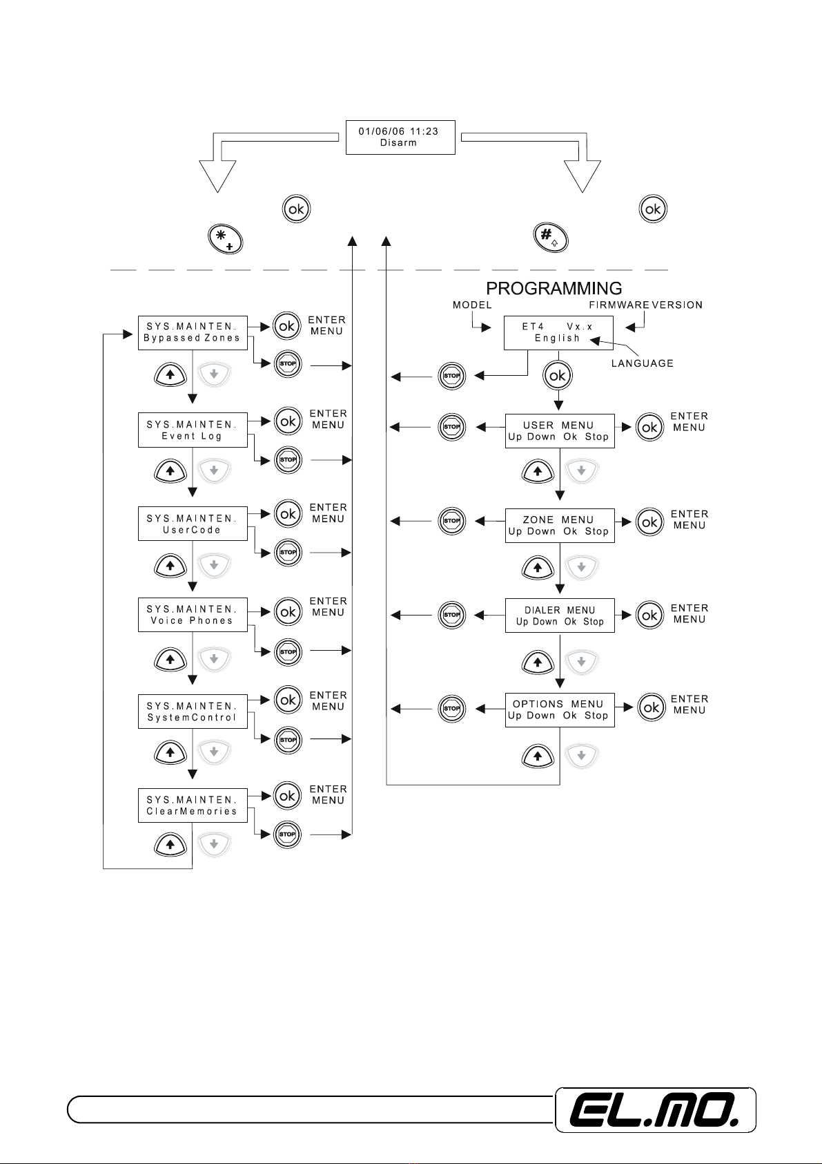
5.3 Setup menu with user code after having setup relevant code
N N N N N N N N
N N N N N N N N
8 FIGURE INSTALLER CODE
IT DOES NOT EXIST BY DEFAULT
IT HAS TO BE CREATED FROM USER CODE
N N N N N N N N
MAINTENANCE
MEN
US
with
ou
t TIME
OU
T
MENUS with TIME OUT
CONTROL MODE CONTROL MODE
Tabla de contenidos
Otros manuales de Unidad de control de Elmo


Manuales populares de Unidad de control de otras marcas

Festo
Festo Compact Performance CP-FB6-E Manual de lista de piezas

Elo TouchSystems
Elo TouchSystems DMS-SA19P-EXTME Manual de usuario

JS Automation
JS Automation MPC3034A Manual de usuario

JAUDT
JAUDT SW GII 6406 Series Guía rápida

Spektrum
Spektrum Air Module System Manual de usuario

BOC Edwards
BOC Edwards Q Series Manual de usuario


