ELAD QSF-06 Manual de usuario

www.eladit.com
ELAD QSF-06
Switchable Preselector Filter Board for FDM-DUO
with Active Switch and Band Select Output
USER MANUAL

ELAD QSF-06 User Manual Rev 1.0 04/2016
© 2016 ELAD S.r.l. All rights reserved. No part of this document may be reproduced, published, used, disclosed or disseminated in any form or
by any means, electronic, photocopying or otherwise, without prior written permission of ELAD S.r.l.
2
Contents
Revision History ............................................................................................................................................ 3
1 Overview ............................................................................................................................................... 4
2 Package Contents.................................................................................................................................. 5
3 Hardware Description ........................................................................................................................... 6
3.1 Front Panel Description ................................................................................................................ 6
3.2 Rear Panel Description.................................................................................................................. 7
3.3 Internal Description ...................................................................................................................... 8
4 Filter Installation ................................................................................................................................... 9
5 ELAD Filter Module Family.................................................................................................................. 11
5.1 FPCB-B3 Module Schematic........................................................................................................ 11
5.2 FPCB-H5 Module Schematic........................................................................................................ 11
6 Band Select Output .............................................................................................................................12
7 Using QSF-06 with the FDM-DUO. ......................................................................................................12
8 QSF-06 Schematic ...............................................................................................................................16
Declaration of Conformity (EC) ................................................................................................................... 18

ELAD QSF-06 User Manual Rev 1.0 04/2016
© 2016 ELAD S.r.l. All rights reserved. No part of this document may be reproduced, published, used, disclosed or disseminated in any form or
by any means, electronic, photocopying or otherwise, without prior written permission of ELAD S.r.l.
3
Revision History
Revision
Date
Description
Rev 1.0
04/2016
First version.

ELAD QSF-06 User Manual Rev 1.0 04/2016
© 2016 ELAD S.r.l. All rights reserved. No part of this document may be reproduced, published, used, disclosed or disseminated in any form or
by any means, electronic, photocopying or otherwise, without prior written permission of ELAD S.r.l.
4
1Overview
ELAD QSF-06 is a switchable preselector that allows the selection between 6 configurable filters. User
can configure the internal board by choosing the right set of filters within the filter module family
provided by ELAD or self-build. The QSF-06 board has also an on board active switch which ensure fast
commutation time between transmission and reception state and a band select output to drive an
external amplifier. Using the ELAD FDM-SW2 SDR software it is possible to configure the FDM-DUO to
automatically select the proper filter as a function of the tuning frequency.
The block diagram here below represents the QSF-06 board.
PTT IN
LED
TX
ANT
RX
Preselector
Filters
1.7MHz High
Pass Filter
DAC
BAND OUT
EXT IO
I2C
control lines
SPI
control lines
PTT control line
RX PATH
TX
PATH

ELAD QSF-06 User Manual Rev 1.0 04/2016
© 2016 ELAD S.r.l. All rights reserved. No part of this document may be reproduced, published, used, disclosed or disseminated in any form or
by any means, electronic, photocopying or otherwise, without prior written permission of ELAD S.r.l.
5
2Package Contents
ELAD QSF-06 package contains:
QSF-06 switchable pre-selector board with FBPY bypass module already installed in slot number
6 (see section 3.3 - Internal Description for details),
one 3.5mm male to male jack cable,
one DB9 male to male flat cable,
two coaxial cables with PL259 UHF connectors,
rubber feet,
user manual.

ELAD QSF-06 User Manual Rev 1.0 04/2016
© 2016 ELAD S.r.l. All rights reserved. No part of this document may be reproduced, published, used, disclosed or disseminated in any form or
by any means, electronic, photocopying or otherwise, without prior written permission of ELAD S.r.l.
6
3Hardware Description
3.1 Front Panel Description
1 –Filter LEDs
Selected filter indication. When a filter is in use, the corresponding LED turns on.
2 –State LEDs
Indication of the current state. The TX led turns on when transmitting and the RX led turns on when
receiving .
3 –EXT I/O
DB9 female connector that allows communication with the FDM-DUO.
This is NOT a standard serial port.
Pin 1: SPI Latch
Pin 2: I2C SCL
Pin 3: SPI Clock
Pin 4: I2C SDA
Pin 5: Ground
Pin 6: Not Connected
Pin 7: Not Connected
Pin 8: SPI Data
Pin 9: +5V
4 –BAND
3.5mm stereo jack connector that provides analog voltage to drive a linear power amplifier
(see section 6 - Band Select Output for details).

ELAD QSF-06 User Manual Rev 1.0 04/2016
© 2016 ELAD S.r.l. All rights reserved. No part of this document may be reproduced, published, used, disclosed or disseminated in any form or
by any means, electronic, photocopying or otherwise, without prior written permission of ELAD S.r.l.
7
3.2 Rear Panel Description
1 –PTT IN
3.5mm stereo jack connector that receives transmission and reception information from the FDM-DUO.
2 - TX
SO239 UHF connector. Must be connected to the RTX/TX connector of the FDM-DUO.
3 - ANTENNA
SO239 UHF connector. Must be connected to the antenna.
4 –RX
SO239 UHF connector. Must be connected to the RX connector of the FDM-DUO.

ELAD QSF-06 User Manual Rev 1.0 04/2016
© 2016 ELAD S.r.l. All rights reserved. No part of this document may be reproduced, published, used, disclosed or disseminated in any form or
by any means, electronic, photocopying or otherwise, without prior written permission of ELAD S.r.l.
8
3.3 Internal Description
The picture below show the positions of the six slots. If FBPY bypass module is used, it must be placed in
slot number 6.
ELAD QSF-06 User Manual Rev 1.0 04/2016
© 2016 ELAD S.r.l. All rights reserved. No part of this document may be reproduced, published, used, disclosed or disseminated in any form or
by any means, electronic, photocopying or otherwise, without prior written permission of ELAD S.r.l.
9
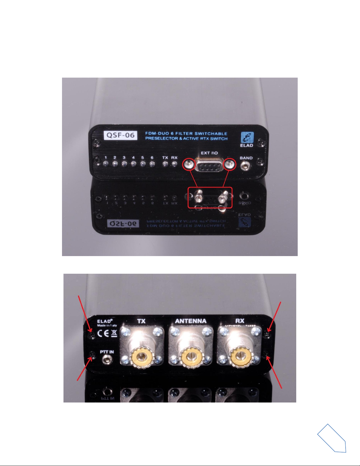
4Filter Installation
To install a new filter it is necessary to open the QSF-06 enclosure. To do that, first remove the two
standoffs of the DB9 connector present on the front panel.
Then, remove the four screws of the rear panel.

ELAD QSF-06 User Manual Rev 1.0 04/2016
© 2016 ELAD S.r.l. All rights reserved. No part of this document may be reproduced, published, used, disclosed or disseminated in any form or
by any means, electronic, photocopying or otherwise, without prior written permission of ELAD S.r.l.
10
Now it is possible to extract the printed circuit board together with the rear panel like shown in the
picture below.
Once extracted, insert the desired filters in the chosen positions. The filter modules have a polarized
connection, i.e. they cannot be inverted because their connectors have a different number of pin.
Al last, relocate the printed circuit board inside the enclosure and screw in the four screws and the two
standoffs.
Tabla de contenidos


