Eightpins NGS2 Manual de usuario

1
EIGHT
PINS
EIGHTPINS
Installation Guide and Manual
Eightpins NGS2
Integrated variable seatpost
V1 15.05.2019
NGS2.0

2
EIGHT
PINS
Inhalt
3 General
3 Warranty Policy
3 Service
5 Safety instructions
5 Assembly and service
5 Modifi cations
5 Before the assembly
6 Part description
7 Compatibilities
9 Installation
19 Manual
21 Manual adjustments
26 Service

3
EIGHT
PINS
General
Thank you for equipping your bike with an Eightpins variable seatpost, a highstandardized, highly technical product for mountain bikes. There is a
variety of points to take into consideration assembling and using the seatpost. As a result of the integration of the seatpost, it is designed entirely dif-
ferent in comparison to other variable seatposts. The adjustment of the seat height as well as the adjustment of the travel of the seatpost is realized
with one single tube. The mechanics for this is directly connected with the frame via the Postpin axle that absorbs all axial forces. The lateral forces
are absorbed by the bushing tubes and thus by the frame. It is therefore crucial to mind the maximal extension as well as the minimum insert length.
Attention! If assembled or used in a wrong way, you may hurt yourself as well as damage the frame or
the seatpost.
Make sure all adjustment elements are in place at all times and that the tension of the cable is adjusted correctly. In case you do not have the skills
to assemble the seatpost, please refer to your local bike dealer or the service center in your country.
Attention! Read the following assembly information and manual carefully and stepby-step and mount
the Eightpins seatpost only according to the instructions.
Warranty Policy
We offer a two-years warranty for your seatpost beginning at the date of purchase. The warranty exclusively includes the repair or exchange of the
components damaged. In order to claim a warranty case, the receipt is obligatory. Common wear, usual services and wrong assemblies are not
covered by the warranty. If the seatpost has been altered in any way, the warranty automatically expires; the rider is responsible for any damages
caused by any alteration of the seatpost.
Service
As to the service, a major advantage of the Eightpins variable seatpost is that the main tube can be dismounted very easily and that the anti-fricti-
on bushing can be cleaned and/ or exchanged quickly. In case you notice a higher friction in the system, it can be greased via a grease ort in the
outer sleeve. With the right tools and a basic technical understanding, you may service the seatpost yourself including cleaning and greasing the
bushings, pumping up the system, readjusting the tension of the overload clutch and exchanging the cable.
In general, not much servicing is required. The locking mechanism does not wear out. In case the gas pressure spring loses pressure, it is to be
sent to us or brought to a local service center, as the sealing needs to be exchanged.

4
EIGHT
PINS
The following service activities have to be done regularly.
Before every
ride
Every 20 opera-
ting hours
Every 40 opera-
ting hours
Every 100 operating
hours
Every 200 opera-
ting hours
Remove dried dirt with
water and mild soap x
Cleaning the wiper x
Cleaning the bushing
tube x
Exchange the bushing
tube x
Exchange the wiper x
Exchange the Felt ring x
Sealing service of the gas
spring x
Oil refi ll x
For services of all kinds, please refer to your local bike workshop or to Lupaan GmbH:
Lupaan GmbH „EIGHTPINS“
Kristein 2
4470 Enns
www.eightpins.at
+43 660 8107143

5
EIGHT
PINS
Attention! Do not service the mechanics or the gas pressure spring yourself as the system is under
high pressure and as one may risk severe injuries.
Safety instructions
Usage as intended
The Eightpins variable seatpost is designed for bicycle frames featuring a Postpin interface. The range of application includes touring bikes, trekking
bikes and mountain bikes. Bicycle frames that do not have this feature should not be modifi ed. The Eightpins variable seatpost must only be assem-
bled and combined with the original Eightpins remote lever. Different leverage ratios can cause irreparable damages.
Assembly and service
The assembly and the service of the Eightpins variable seatpost requires a special understanding of technical matters. Do not overestimate your
own skills but refer to a professional bicycle shop or to an authorized Eightpins service partner at all times. This is the only way a correct service can
be guaranteed.
Modifi cations
The Eightpins variable seatpost is not to be altered in any way. Do not dismount it, sand it down or paint it. Always use a torque wrench where
necessary. Read the manual carefully and follow it step-by-step.
Attention: A seatpost that has not been mounted correctly does not work correctly.This may lead to
crashes and injuries. Besides, the frame can be damaged.
Before the assembly
The post-pin mounting interface in the frame contains an adjustment screw on the right side of the frame for vertical alignment of the seatpost.
This screw is already set at the factory and glued with a detachable screw glue.
If the adjusting screw is not included in the frame or adjusted correctly, contact the frame supplier.
6
EIGHT
PINS
1
2
3
4
5
6
7
89
10
11
12
13
14
15
B ( 1:1)
16
17
18
19
20
21
22
23
24
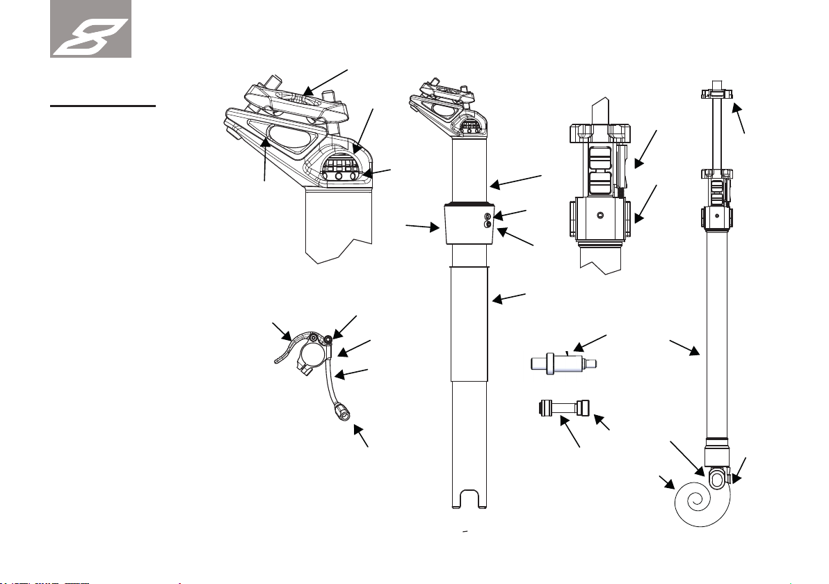
Part description
1 Eightpins Maintube
2 Eightpins Cartridge
3 Bushing
4 Outer sleeve
5 Fixing screw
6 Lubrication port
7 Flex aluminium cable housing
8 Remote lever
9 Cable clamping nut
10 Inline cable adjuster
11 End cap small
12 Special end cap or FlexChain
13 Valve adapter
14 Cable: Eightpins or Campagnolo
15 Postpin axle
16 Seat angle adjuster
17 Height adjuster
18 Seat clamp top
19 Seat clamp bottom
20 Release slider
21 Guiding inserts
22 Height adjusting clamp
23 Mounting interface
24 Adjusting ring

7
EIGHT
PINS
Compatibilities
The integrated Eightpins variable seatpost is exclusively designed for frames with a Postpin interface. One can not retrofi t this interface to a bicycle
frame. Refer to your local bike shop in case you are in doubt.
Attention: Eightpins decisively advices its customers not to modify a frame in any way, as this can weaken the
frame, cause crashes and lead to severe injuries including death.
Eightpin‘s seatposts are divided into two different size schemes. There is a size scheme with 4 sizes: S, M, L and XL and a size scheme with 6
sizes: XS, S, M, L, XL, XXL. The size to use depends entirely on the frame size.
Use only Eightpins cartridges of the correct size for the appropriate frame size. (Example: 6X-L cartridge fi ts into a frame with 6-fold size scheme
with the size L)
The bushing tube length is selected so that it corresponds to the minimum insertion depth of the seattube in the frame. All bending forces are trans-
ferred to the frame via the bushing tube. When assembling or exchanging the bushing tube, the correct length must be used.
The respective length can be found in the table under the column bushing tube.
It is also important to pay attention to the compatibility of the seatpost tube lengths. The table contains all possible combi-
nations. The corresponding adjustment ranges can also be found in the table. The values refer to the distance between the
bottom bracket and the upper edge of the saddle. Included is a saddle with a height of 4cm.
ATTENTION! Only the intended and compatible seat post sizes, strokes and bushing tube
lengths specifi ed by the bike manufacturer may be used.
HP
LP

8
EIGHT
PINS

9
EIGHT
PINS
Installation
Frame/seattube
Cable housing / bowden insallation
Install the cable housing in the frame before installing the seat post. Please follow the instructions of the frame manufacturer. The cable housing is
to be inserted into the seat tube until about 2 cm of it reach out of it. The second end of the housing – at the top of the frame – is to be cut depen-
ding on the frame size. The cable housing is pushed further out of the frame during assembly of the seat post by the length X. Observe the following
table when cutting the cable housing and shorten it to the desired length.
The frame must have a 5mm hole at the top of the seat tube to mount and fi x the outer sleeve. If this hole does not
exist, refer to the manual of the frame supplier to fi nd out how to drill this hole in the seat tube of the frame.
ca. 20mm
Länge X
length X
Länge X
length X

10
EIGHT
PINS
Endcap
Installation of the seatpost
There are two different types of end caps which can be fi tted to the end of the outer cable at the seattube side. Left
picture shows the special end cap of Eightpins. This is mainly used in non-e-bikes. The right picture shows the Lukon
Flex chain end cap version which is mainly used for e-bikes. This ersion allows a cable routing with very narrow radius
around the interface. This is needed if the space between electric motor and seat post is tight and limited.
Insert the cable into the ca-
ble housing until it reaches
out of it again at the top of
the frame.
Push the bushing tube
and the outer sleeve to the
lower end of the seatpost.
Hang the cable housing on
the cable housing coun-
terpart at the Postpin moun-
ting unit at the lower end of
the Eightpins
capsule.
Tension the cable at the
front end of the cable
housing and carefully insert
the seatpost into the seat
tube of the
frame.
Tabla de contenidos
Otros manuales de Accesorios para bicicletas de Eightpins


Manuales populares de Accesorios para bicicletas de otras marcas

Sigma
Sigma BC 16.16 Manual de usuario

Playcore
Playcore Dero Setbacks Manual de usuario

VDO Cyclecomputing
VDO Cyclecomputing x3dw Manual de usuario

Cateye
Cateye RAPID X2 Manual de usuario

buratti meccanica
buratti meccanica Clorofilla Trail Manual de usuario

Shimano
Shimano SG-8R20 Instrucciones de funcionamiento


