EDS SK120 Manual de usuario

SK120
Standalone Keypad
ACCESS CONTROL SYSTEM
www.edselectronic.com
Warranty Certicate & User Manual

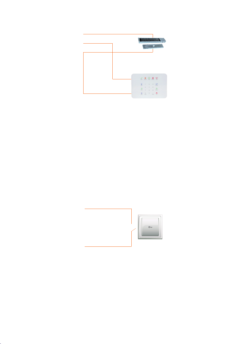
SK120 Standalone Keypad is a security solution that provides entrance control without
a key. Up to 120 users can be dened via SK120’s keypad. User security is prioritized
against possible unauthorized access thanks to its trap password feature. Allowing
short-term entrance with the 24-hour temporary password, SK120’s mounting and
installation are easy
Conrmation
RFID
Cancel and
Back Button
Settings Indicator Menu Indicator
Ergonomic and modern design with its features which are touch keypad, LED indicators,
and lighting.
120 users are dened.
A password and/or card be dened for each user.
User safety is at the forefront; Allows for each user to dene a trap password as well.
Be used with Proximity card.
Access permission is in 4 different ways: Password only, card only, card and password
card or password.
Temporary access 24-hour is allowed for guests.
Adjustable relay contact from 1 second to 60 seconds
DESCRIPTION
1
SPECIFICATIONS
2
1

Model SK120
Environmental class II Indoor
Electrical
Supply voltage 12-30V DC
Stand-by current <53mA (12V DC)
Operating current <163mA (12V DC)
Functional
User password digit 4-6 digits
Number of user passwords 120
Number of RFID cards 120
Relay output time 1 to 60 seconds
Indicators and Warnings
Indicators 2 LED indicator; settings and operation LED
Tamper Available (Wall)
Buzzer Available
Lighting Lighting turns on when you hover over the device
Keyboard Touch
Modes
1Password
2Password and RFID Card
3RFID Card
4 Password or RFID Card
General
Housing material ABS Plastic
Housing shape Standard
External cover color Black
Operating temperature -10ºC / +50ºC
Operating humidity 15 - 90 %RH
Dimensions (HxWxD) 90x70x25mm
Weight 73g
Production Year The rst 2 digits of the serial number on the product indicates the production year and the
next 2 digits show the production week (The number on the product label).
Manufacturer EDS Elektronik Destek Sanayi ve Ticaret Ltd.
Meclis Mah. Teraziler Cad. Hayran Sk. No: 4 34785 Sancaktepe / İstanbul / Turkey
Recycling
Factory Values
Master password 123456
Relay time 2 seconds
Mode 4 (Password or RFID Card)
Trap password 0
TECHNICAL SPECIFICATIONS
3
2

12V-30V DC and GND connections should be made from the place shown in the above
gure.
NO COM connection is used to connect SK120 device to magnetic door lock. For
entrance, the door is unlocked by entering the password.
NC COM connection allows the SK120 to be used as a keypad for alarm panels. The
connection is made as shown below.
MOUNTING
4
Electrical Connections
Buzzer
Key
Reset Jumper
Connector
1
1
4
2
3
2
3
4
3
12V GND
TAMPER BUTTONPANIC
NC C NO
Notation Description
12V + 12-30V DC connection
GND Earth connection
NC/C/NO Relay Output
TAMPER Tamper connection
PANIC Panic button connection
BUTTON Button connection
Device Supply
Relay Output
It is recommended to install with 4 dowels and screws. There are 2 ways to mount the
device. The surface to be mounted must be clean and flat. It is recommended to mount
the product at eye level.
It is used to transmit information to alarm panels via NC dry relay connection in cases
where the device’s tamper situation is without the user’s knowledge or request.
In emergencies such as opening the door under threat; the trap password can be entered
after the password, this means a negative trigger to the panic exit is given. The device
can be connected to other devices that have a negative trigger input like an alarm panel
and a siren from this connection.
It is used by connecting to the door automatic switch so that the magnetic locked door
can be opened by the non-keypad.
NO
Buton +
Door Automatic
Switch
magnetic door
lock
Alarm Panel
Buton -
NC
COM
Wall Mounting
4
Tamper Connection
Panic Output
Button Connection

Use the mounting holes below to mount the device on the wall.
Close the top cover of the product whose assembly is completed.
Mount the screw to the top cover.
Dowel Installation
Mounting Screwing Location
Top Cover and Bottom Cover
Installation Location
Nail Insertion
Screwing Location
Drill your masonry
with a masonry drill bit
Hit the screw suitable for the
plastic anchor from the back
with a hammer
Tighten it with a
screwdriver is done
Take the dust out of the wall
you pierced with the help of air
Hammer your plastic
anchor into the wall you
pierced
5
Mounting Type 1
A
A
C
B
D
A
AA
B
C
C
D

Assemble the back cover of the device and the wall mounting apparatus, paying attention
to the direction of the arrows shown below gure. For the correct position, turn the wall
mounting apparatus clockwise until the cover of the device comes from point E to point
F. Close the cover of your device from the tabs and screw it.
Bring the wall-mounted device onto the apparatus with the screwing completed. Turn it
clockwise.
Repeat the assembly cover closing tab steps of Type 1.
Run the cables through the cable space shown in the middle. Make the cable connection.
Pay attention to the direction of the arrows while mounting on the wall. Mount the rear
bracket to the wall as shown below.
6
Mounting Direction Indicator 1
Mounting Direction Indicator2
Cable Entry Wall
Screwing Space
F
E
E
G
F
H
H
H
H
G
H
Mounting Type 2

You can enter the programming settings with your main user password. Settings
indicator lights up on the device in this menu.
7
No Name Description
1 Add User 1- Add Password
2- Add RFID
1-1 Add Password Enter User Number - Enter Password - Conrm
1-2 Add RFID Enter User Number - Read Card - Conrm
2 Delete User 1- Delete Password
2- Delete RFID
2-1 Delete Password Enter User Number - Conrm
2-2 Delete RFID Enter User Number - Conrm
3Relay Time 1- 60s Duration Select - Conrm
4Usage Type Setting 1-2-3-4 Select Usage Type - Conrm
5 24-Hour Password 1- Add 24-Hour Password
2- Delete 24-Hour Password
5-1 Add 24-Hour Password Enter Password - Conrm
5-2 Delete 24-Hour Password Conrm
6 Trap Password Programming 1- Add Trap Password
2- Delete Trap Password
6-1 Add Trap Password Enter User Number - Write trap Password up to 0-9 - Conrm
6-2 Delete Trap Password Enter User Number - Conrm
7 Sound Level
1- Low
2- Medium
3- High
PROGRAMMING
5
Menu Diagramme
When an incorrect entry is made (For example, when a user number greater than 120
is added), an error tone sounds. After this step, it is expected to be re-entered correctly.
It does not exit the programming settings.
Pressing the back button in any step returns to the Programming menu. Pressing the
back button again exits the programming settings.
After adding a password or RFID, it returns to the step where ID is entered to add a
password again. Pressing the back button twice will exit this menu.
After conrming any step in the menu, the device returns to the entry section in the
programming menu.
Notes:

You can use the device in 4 different ways. Below you can nd the settings of the usage
types and accordingly you can choose the most suitable setting for you.
It is set to password or RFID, the default usage type 4. For use type 2, rst RFID card and
then password should be read.
Operation and settings indicator lights up for the rst time. When the master user
password is changed, the unlock conrmation and settings indicator turns off and
the device returns to normal.
The main user password must be changed at rst startup.
No Operation Key Sound and Indicators Description
1
Access to
programming
settings
Conrm Key /
Master user password
/ Conrm Key
The two beeps are the
same length. The yellow
settings indicator lights up.
The programming settings
are entered with the new
master user password.
2Usage Type Menu 4
Two beeps indicate
conrmation at the same
length.
The method of use is
entered in the selection
menu.
3
Usage Type
selection
menu
Usage Type selection
to 1-4 / Conrm
Key
Two beeps indicate
conrmation at the same
length. Returns to the
programming menu.
Default usage pattern 4
1: Password
2: Password + RFID
3: RFID
4: Password or RFID from 1
to 4 are selected.
4
Exiting the
programming
settings
Back key
3 beeps emit from
programming settings of
the same length. The yellow
settings indicator turns off.
The programming settings
are exited.
8
Usage Type Number Description
Password 1It only activates login with password.
Password + RFID Card 2The password and RFID card are read at the same time
and entry is provided.
RFID Card 3It only activates access with RFID card.
Password or RFID Card 4 When any of the password or RFID cards is read alone,
an entry is provided.
Setting the Way of Use
No Operation Key Sound and Indicators Description
1
Access to
programming
settings
Conrm key /
123456/
Conrm key
The two beeps are the
same length
The programming settings
are entered with the default
master password.
2New main user
set password
6 digit password is
entered /
Conrm Key
Two beeps indicate
conrmation at the same
length. The yellow settings
indicator turns off.
The new master password is
created. It must be 6 digits.
Register this password.
Changing the Master User Password
First Opening

No Operation Key Sound and Indicators Description
1
Access to
programming
settings
Conrm key /
Master user password /
Conrm Key
The two beeps are the
same length. The yellow
settings indicator lights up
The programming settings
are entered with the new
master user password.
2Add user menu 1
Two beeps indicate
conrmation at the same
length.
Enter the add user
menu.
3User code
registration menu 1Two beeps indicate conr-
mation at the same length.
The user code is entered in
the registration menu.
4 User number User number /
Conrm Key
Two beeps indicate conr-
mation at the same length.
Enter the user code between
1 and 120.
5Enter password Enter password /
Conrm Key
Two beeps indicate
conrmation at the same
length.
Password between 4-6
digits is entered.
6 Repeat password Enter password /
Conrm Key
Two beeps indicate conr-
mation at the same length.
Goes back to step 4 with
the sound of adding again.
The password is repeated.
No Operation Key Sound and Indicators Description
1
Introduction to
Programming
Settings
Conrm key /
Master user pasword
/ Conrm Key
The two beeps are the
same length. The yellow
settings indicator lights
up.
The programming settings
are entered with the new
master user password.
2Add user menu 1
Two beeps indicate
conrmation at the same
length.
Enter the add user
menu
3RFID registration
menu 2
Two beeps indicate
conrmation at the same
length.
The user code is entered in
the registration menu.
4 User number User number /
Conrm Key
Two beeps indicate
conrmation at the same
length.
User number is entered in
1-120.
5Identifying the card Card is swiped /
Conrm Key
Two beeps indicate
conrmation, then returns
to step 4 with the adding
sound.
Please bring the card closer.
Add User Password Record
Add User RFID Card
To add multiple users, press 2 after 5.
Up to120 users can be added. You can write the user number in the note section at
the end of the user manual.
After adding the password, it is continued to add the password from step 4.
9
Tabla de contenidos


