Echoflex Installation Guide
Tri-Zone Dimming Controller
Tri-Zone Dimming Controller Page 7 of 8 Echoflex
Test the Controller
Echoflex provides the controller in either a pre-commissioned state or a
factory default state.
• Pre-commissioned devices are linked, configured, and labelled
according to customer specifications. When powered up, the LEDs
repeat a blink code by color to indicate the type and number of
devices currently linked to each channel. See Blink Codes and
Operations on page 7. To test the relay(s), press the [Learn] button
or use a linked switch.
• In factory default state, when powered up, the Power LED displays
solid red to indicate the controller has no linked devices. To test the
relay(s), press the [Learn] button or link a switch. See relevant switch
documentation.
A maximum of 20 switches or sensors can be linked to one controller.
Blink Codes and Operations
The tables below describe the controller's blink codes and operating activity
for each channel by LED color. Long blinks=type. Short blinks=count.
Red is for Channel 1, Green is for Channel 2, and Blue is for Channel 3.
Blink Codes
*An occupancy sensor linked to any channel will appear to be linked to all three channels.
**A photo sensor linked to Ch1 or CH2 will appear to be linked to both channels.
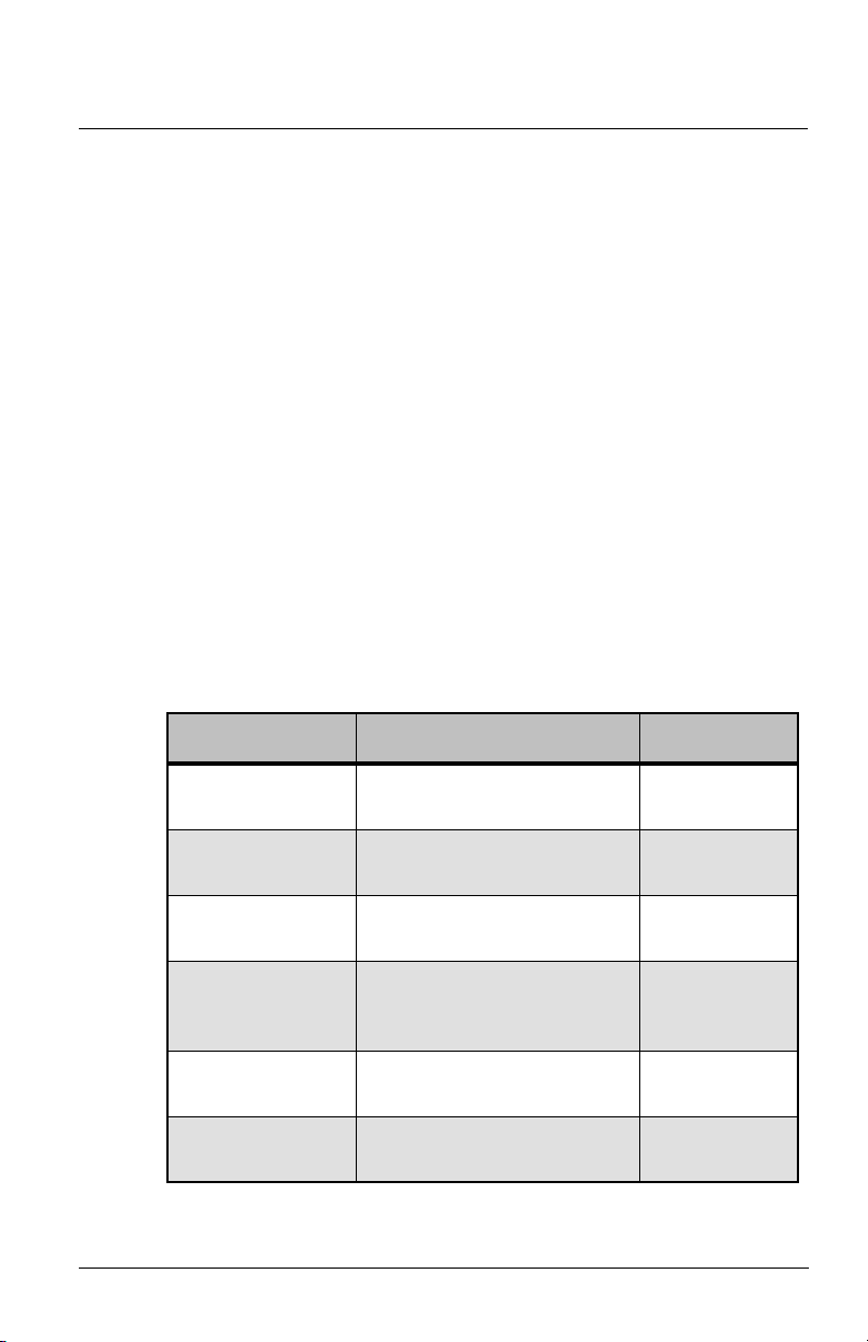
Description Power LED Learn LED
Factory default
(links only) On solid (red) Off
Switch(es) 1 long blink followed by
short blinks counting switches Off
Occupancy
sensor(s)*
2 long blinks followed by
short blinks counting sensors Off
Photo sensor**
(max 1)
3 long blinks followed by 1
short blink counting sensor
(displays in Ch1 and Ch2)
Off
Central command 4 long blinks followed by
short blinks counting devices Off
Demand response 5 long blinks followed by
short blinks counting devices Off