E Star HERF-600 Manual de instrucciones

www.estarpower.com
Installation/User Manual
MICROINVERTER
Ver:1.1,2022-07
HERF-600 HERF-800 HERF-1000

202207V1.1
1
www.estarpower.com
About Microinverter
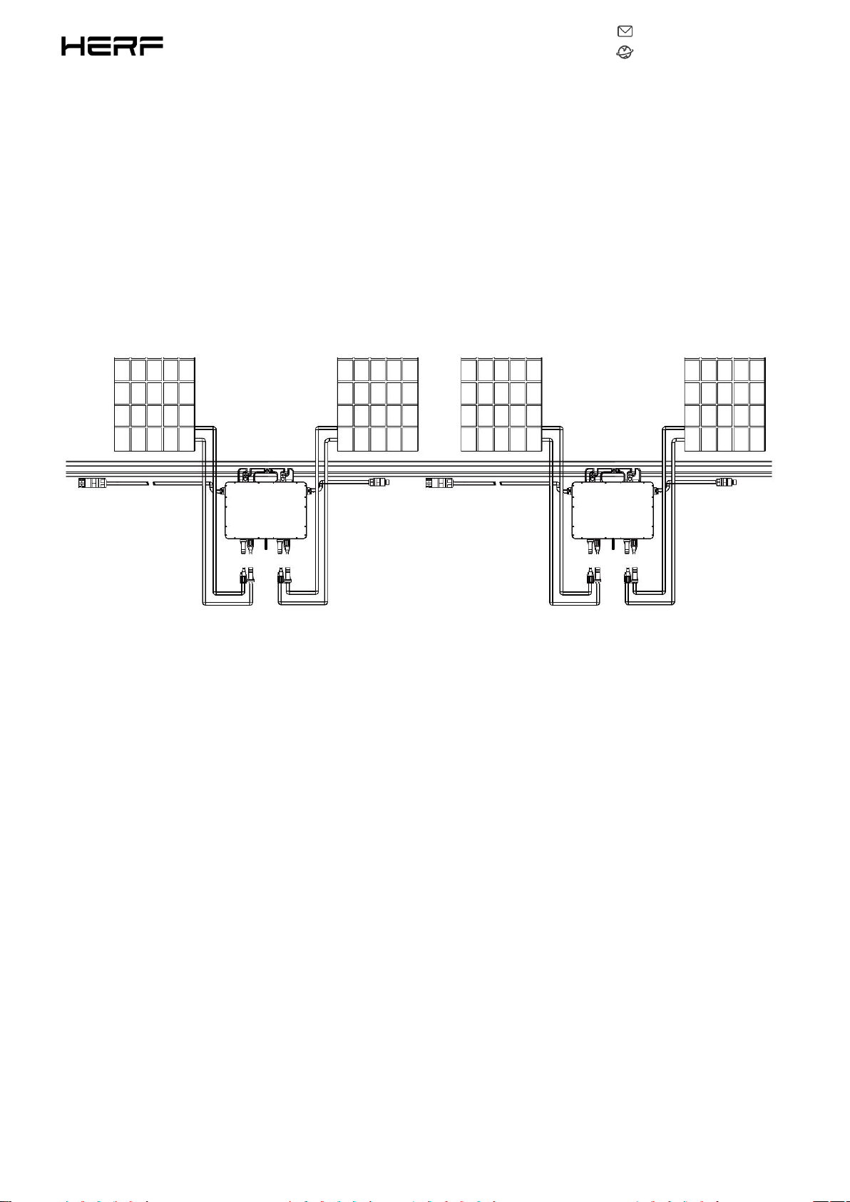
This system is composed of a group of Microinverters that convert direct current (DC) into alternating current
(AC) and feeds it into the public grid. The system is designed for the incorporation of one Microinverter for
four photovoltaic modules. Each Microinverter works independently that guarantees the maximum power
generation of each photovoltaic module. This setup enables user to control the production of a single
photovoltaic module directly, consequently improving the flexibility and reliability of the system.
About the Manual
This manual contains important instructions for the HERF-600/HERF-800/HERF-1000 Microinverter and must
be read in its entirety before installing or commissioning the equipment. For safety, only qualified technician,
who has received training or has demonstrated skills can install and maintain this Microinverter under the
guide of this document.
Other Information
Product information is subject to change without notice. User manual will be updated frequently, please refer
to HERF official website at https://www.estarpower.com/microinverters /for the latest version.

202207V1.1
2
www.estarpower.com
Table of Contents
1.Important Safety Instructions....................................................................................................................................................3
1.1Safety Instructions........................................................................................................................................................... 3
1.2Radio Interference Statement......................................................................................................................................... 4
1.3The Meaning of Symbols................................................................................................................................................. 5
2.Microinverter System Introduction........................................................................................................................................... 6
2.1About 2 in 1 Unit..............................................................................................................................................................6
2.2Microinverter Highlights.................................................................................................................................................. 6
2.3Terminals Introduction.................................................................................................................................................... 7
3.About Function.......................................................................................................................................................................... 8
3.1Work Mode...................................................................................................................................................................... 8
4.About Installation...................................................................................................................................................................... 9
4.1Accessories.......................................................................................................................................................................9
4.2Installation Precaution.....................................................................................................................................................9
4.3Space Distance Required............................................................................................................................................... 10
4.4Preparation.................................................................................................................................................................... 10
4.5Installation Steps............................................................................................................................................................11
5. Troubleshooting...................................................................................................................................................................... 17
5.1Status LED Indicator.......................................................................................................................................................17
5.2On-site Inspection (For qualified installer only)............................................................................................................17
5.3Routine Maintenance.................................................................................................................................................... 18
6.Decommissions........................................................................................................................................................................ 19
6.1Decommissions..............................................................................................................................................................19
6.2Storage and Transportation........................................................................................................................................... 19
6.3Disposal..........................................................................................................................................................................19
7.Technical Data.......................................................................................................................................................................... 21
7.1DC Input......................................................................................................................................................................... 21
7.2AC Output...................................................................................................................................................................... 21
7.3Efficiency, Safety and Protection................................................................................................................................... 21
7.4Mechanical Data............................................................................................................................................................ 22
7.5Features......................................................................................................................................................................... 22
Appendix 1:................................................................................................................................................................................. 23
Installation Map.................................................................................................................................................................. 23
Appendix 2:................................................................................................................................................................................. 24
WIRING DIAGRAM – 230VAC SINGLE PHASE:.................................................................................................................... 24
WIRING DIAGRAM – 230VAC / 400VAC THREE PHASE:..................................................................................................... 25
WIRING DIAGRAM –120VAC / 240VAC SPLIT PHASE:........................................................................................................ 26
WIRING DIAGRAM – 120VAC / 208VAC THREE PHASE:..................................................................................................... 27

202207V1.1
3
www.estarpower.com
1.Important Safety Instructions
This manual contains important instructions to follow during installation and of the Photovoltaic Grid-connected
Inverter (Microinverter). To reduce the risk of electrical shock and ensure the safe installation and operation of
the Microinverter, the following symbols appear throughout this document to indicate dangerous conditions and
important safety instructions.
Specifications subject to change without notice - please ensure you are using the latest manual found at the
manufacturer website.
WARNING: This indicates a situation where failure to follow instructions may cause a serious hardware failure or
personnel danger if not applied appropriately. Use extreme caution when performing this task.
*Note: This indicates information that is important for optimized microinverter operation. Follow these
instructions strictly.
1.1Safety Instructions
DO NOT disconnect the PV module from the Microinverter without disconnecting the AC power.
Only qualified professionals should install and/or replace the Microinverters.
Perform all electrical installations in accordance with local electrical codes.
Before installing or using the Microinverter, please read all instructions and cautionary markings in the
technical documents and on the Microinverter system and the Microinverter solar-array.
Be aware that the body of the Microinverter is the heat sink and can reach a temperature of 80℃ . To reduce
risk of burns, do not touch the body of the Microinverter.

202207V1.1
4
www.estarpower.com
DO NOT attempt to repair the Microinverter. If it fails, contact technical support to obtain an RMA number and
start the replacement process. Damaging or opening the Microinverter will void the warranty.
Caution!
The external protective earthing conductor is connected to the inverter protective earthing terminal through AC
connector.
When connecting, connect the AC connector first to ensure the inverter earthing then do the DC connections.
When disconnecting, disconnect the AC by opening the branch circuit breaker first but maintain the protective
earthing conductor in the branch circuit breaker connect to the inverter, then disconnect the DC inputs.
In any circumstance, do not connect DC input when AC connector is unplugged.
Please install isolation switching devices on the AC side of the inverter.
1.2Radio Interference Statement
CE EMC Compliance:The equipment can comply with CE EMC, which are designed to protect against harmful
interference in a residential installation. The equipment could radiate radio frequency energy and this might cause
harmful interference to radio communications if not following the instructions when installing
and using the equipment. But there is no guarantee that interference will not occur in a particular installation. If
this equipment causes harmful interference to radio or television reception, the following measures might resolve
the issues:
A) Relocate the receiving antenna and keep it well away from the equipment.
B) Consult the dealer or an experienced radio / TV technical for help. Changes or modifications not expressly
approved by the party responsible for compliance may void the user's authority to operate the equipment.

202207V1.1
5
www.estarpower.com
1.3The Meaning of Symbols
Symbol
Usage
Treatment
To comply with European Directive 2002/96/EC on waste Electrical and Electronic Equipment and
its implementation as national law, electrical equipment that has reached the end of its life must
be collected separately and returned to an approved recycling facility. Any device no longer
required must be returned to an authorized dealer or approved collection and recycling facility.
Caution
Do not come within 8 inches (20cm) of the microinverter for any length of time while it is in
operation.
Danger of high voltages
Danger to life due to high voltage in the microinverter.
Beware of hot surface
The inverter can become hot during operation. Avoid contact with metal surfaces during
operation.
CE mark
The inverter complies with the requirements of the Low Voltage Directive for the European
Union.
Read manual first
Please read the installation manual first before installation, operation and maintenance.
202207V1.1
6
www.estarpower.com
2.Microinverter System Introduction
2.1About 2 in 1 Unit
“ 2-in-1 Unit Microinverter ” with ultra-wide DC input operating voltage range (16 V – 60 V) and low
start-up voltage (22 V only).
2.2Microinverter Highlights
Maximum output power up to 600W/800W/980W; Adapted to 60 & 72 cells PV panels.
CEC weighted efficiency 96.50%.
MPPT efficiency 99.5%.
High reliability: NEMA6 (IP67) enclosure; 6000V surge protection.

202207V1.1
7
www.estarpower.com
2.3Terminals Introduction
Object
Description
A
AC Connector (Male)
B
DC Connectors
C
AC Connector (Female)

202207V1.1
8
www.estarpower.com
3.About Function
3.1Work Mode
Normal: Under this mode, Microinverter is operating normally and convert DC power into AC power to support
the house loads and feed in to Public Grid.
Zero Export Control: Under this mode Microinverter’s generation is limit base on the current house loads, there
will be no extra power feed in to the Public Grid.
Stand by: There are several circumstances that Microinverter will stay in Standby mode:
The current condition is contradicted with Microinverter operating requirement.
No house loads or the Export control value has been set as “0” on the DCU under the Zero Export Control
mode.

202207V1.1
9
www.estarpower.com
4.About Installation
4.1Accessories
*Note: All accessories above are not included in the package, and need to be purchased separately.
Please contact our sales representative for the price. (M8 screws need to be prepared by
installer-self.)
4.2Installation Precaution
Please install the Microinverter and all DC connections under the PV module to avoiding direct sunlight,
rain exposure, snow layup, UV etc. Allow a minimum of 2 cm of space around the microinverter enclosure
to ensure ventilation and heat dissipation.
*Note: For some countries the DCU will be required to meet the local grid regulation (e.g., G98/99
for UK etc.)
Object
Description
A
AC End Cable (Male), 2m 12AWG Cable
B
DC Extension Cable, 1m
C
M8*25 screws
D
AC Female End Cap, IP68
Este manual sirve para los siguientes modelos
2
Tabla de contenidos
Otros manuales de Inversor de E Star


