Dynamode 2 PORT GIGA SWITCH Manual de usuario

VLAN Ethernet Switch
User’s Manual
Ver. 9.0
Dynamode Ltd

1
Table of Contents
1. Brief Introduction of the product ----------------
2. Networking connection -----------------------
3. Connect with other Switch/Hub -------------
4. Application ------------------------------------
5. LED introduction -------------------------
6. Product Specification ----------------------
7. Management and software introduction ------
7-1 Status Menu --------------------------------
7-1-1 Overview --------------------------------
7-1-2 Port Status -------------------------------
7-2 Configuration Menu ----------------------
7-2-1 Port setting -------------------------------
7-2-2 Port trunking setting ------------------------
7-2-3 Overrall setting --------------------------
7-2-4 QoS setting ------------------------------
7-2-5 Priority Tag remove/insert ------------
7-2-6 VLAN overall setting -----------------
7-2-7 VLAN setting
7-2-8 IGMP snooping------------
7-3 Security setting ------------
7-4 Diagnostic function --------
7-5 Reset to default configuration ---------
Dynamode Ltd

2
7-6 Save configuration ---------------
1. Brief Introduction of the product
This is a 24 x 10/100Mbps + 2 x 10/100/1000Mbps managed
fast switch. This switch supports many advanced features like
supporting 10/100Mbps half/full duplexe auto negotiation,
MD/MDI-X auto sense, Port-VLAN and Tag-VLAN,
bandwidth control management ect.. It is an ideal choice for
users who are seeking for a higher standard networking
connection with a reasonable price.
2. Networking connection
Connect a device to the switch
When the switch is connected with a 10-base Tx device , pls
use UTP Cat 3 or 5 cable
The length of the cable should comply with the IEEE
standards and max. 100 meters (328ft)
If the switch has a Tx fibre port, you can use long range
fibre to connect the switch. The switch supports
MD/MDI-X auto sense, so you can use straight cable to
connect the workstation or another switch/hub.
Dynamode Ltd
3. Connect with other Switch/Hub
The switch can connect with any 10Mbps or 100Mbps
switch/hub. Since all ports support MD/MDI-X auto sense, so
you can use straight cable or UTP cable to uplink the switch
through any port with other switch/hub.
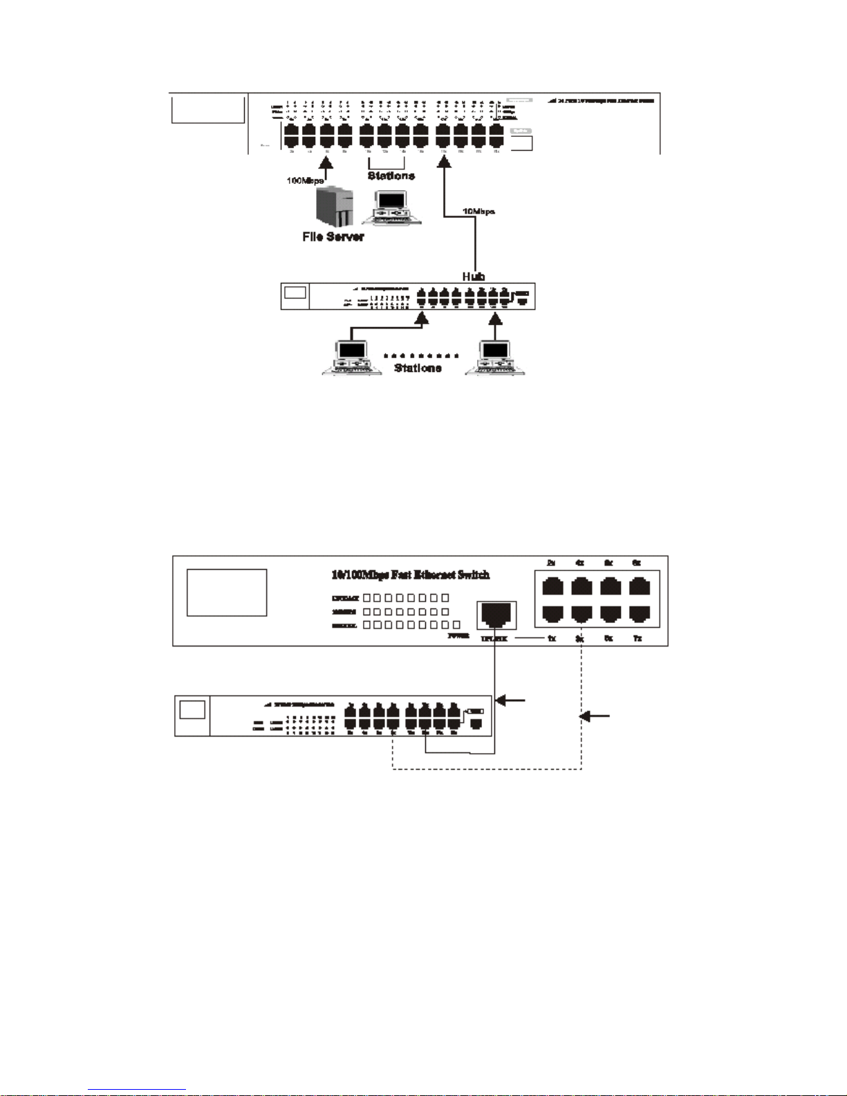
4. Application
The switch can overcome the restriction of hub for uplink, and
improve the overall capacity and performance of the
networking. It can analyse the target address of the dada packet
to decide the forwarding destination of each packet. So the
switch can significately reduce the data flow in the networking.
3
Dynamode Ltd

Below figure shows the segmentation ability of the switch. The
channel dispute of each node is reduced to the minimum, and
the usability of each port is efficiently improved.
5. LED introduction
LED indicator
LED indicators provide some useful information like status of
the switch and each port.
LED status introduction:
LED Name Status Description
4
Off No powerPower On Power on
On
There is a device linked to
the corresponding port but
no activity
Link/Act
Flash
There is an active device
linked to the corresponding
port
On The device in 100Mbps100M bps
Off The device in 10Mbps
Dynamode Ltd

5
On Transfer in full duplexDuplex Off Transfer in half duplex
Giga port LED status introduction
6. Product Specification
-STANDARDS:IEEE802.3 10BASE-TxIEEE802.3u 100BASE
-Tx, IEEE802.3ab 1000BASE-Tx, IEEE802.1p,
IEEE802.1Q
-RATE: 10/100/1000Mbps RJ-45
-MODE: full/half duplex
-MEDIA: 10BASE-Tx UTP Cat 3,4,5; 100BASE-Tx UTP
Cat 5; 1000BASE-Tx UPT Cat 5e.
-PANEL LED: Power, Link/Act, 100Mbps, Duplex
-PORTS: 24 ports 10BASE-Tx/100BASE-Tx RJ45, 2
1000BASE-Tx RJ45
MDI-X/MDI: Auto sense
VLAN: Yes
QoS: Yes
TRUNK: Yes
Bandwidth Control: Yes
7. Management and software introduction
This switch support VLAN, Trunk, QoS, Ports
configuration (enable/disable, auto negotiation, half/full duplex,
flow control) ect. networking management functions. It can be
managed by management software through serial port(RS-232)
or browser.
Management through console port
Dynamode Ltd

Before the management, pls follow below steps:
1. Connet the switch console port with the PC serial port
(RS-232) through the cable enclosed.
2. Run the hyper terminal software of the windows. If your
PC hasn’t installed the hyper terminal software, pls
install it under “ control panel ----> add/delete software
---> Windows installation software ----> Communication
---> Hyper terminal” (Windows 98). For Windows 2000
the hyper terminal is intalled by default.
3. Input the name for the connection in the new link
dialogue.
4. Set the COM port according to the PC main board
( usually COM1).
6
Dynamode Ltd

5. Serial port settings:
Bit rate: 19200bps
Data location: 8
Parity check: None
Stop bit: 1
Flow control: None
7
Dynamode Ltd

After setting, switch on the power of the switch. The
software starts and enter into the log interface below:
Note:
If the hyper terminal interface has disorder words or no
reaction, pls check the serial port property settings, and if
the serial port is correctly connected or if the power of
the switch is on.
Input any key to enter into the main menu. See below
figure:
8
Dynamode Ltd

Note:
When you finished the settings/configuration, pls choose
“save” to save them. After finishing all settings, restart
the switch to effect the settings.
Key explanation:
Digital keys: choose the relative option;
F : Refresh the current page;
There are 6 options on the main menu, for details pls see
below:
7-1 Status Menu
See figure below:
9
Dynamode Ltd
Tabla de contenidos
Manuales populares de Enrutador de red de otras marcas


NETGEAR
NETGEAR FS526T - Switch Manual de usuario

Korenix
Korenix JetNet 5710G Series Manual de usuario

Automated Logic
Automated Logic ZN551 Manual del propietario

Cisco
Cisco ASR 1000 Series Manual del operador

EnGenius
EnGenius ESR-9710 Manual de usuario

Cisco
Cisco 805 Series Instrucciones de funcionamiento y seguridad