DPS Turbonator VGT Manual de usuario

Page 1 of 25
Revision 2.6
Revision Date 6/7/2021 Turbonator® VGT Controller
www.dieselpowersource.com
DPS
Turbonator® VGT Controller
Installation Manual

Page 2 of 25
Revision 2.6
Revision Date 6/7/2021 Turbonator® VGT Controller
www.dieselpowersource.com
* IMPORTANT *
DO NOT CHANGE THE SOFTWARE SETTINGS AND
TUNING UNTIL YOU HAVE DRIVEN THE VEHICLE
AND EVERYTHING IS WORKING PROPERLY!
DO NOT CLOCK OR LOOSEN ACTUATOR, IT IS PRE-
CALIBRATED! DOING SO WILL MAKE VEHICLE RUN
POORLY!
DO NOT INSTALL CRANK SENSOR WIRE UNTIL
VEHICLE HAS BEEN DRIVEN AND IS FUNCTIONING
PROPERLY!
ACTUATOR MUST NOT BE PLACED ON TOP OF OR
ABOVE THE TURBO OR EXHAUST MANIFOLD!
HEAT RISES AND CAN RUIN THE ACTUATOR!
THE SOFTWARE, TUNING, AND ACTUATOR POSITION ARE ALREADY
CUSTOMIZED AND PROGRAMMED FOR YOUR APPLICATION. DPS
CHARGES $150 PER HOUR FOR CUSTOM TUNING. CHANGES MADE TO
SOFTWARE SETTINGS AND TUNING BY UNQUALIFIED INDIVIDUALS
MAY RESULT IN POOR VEHICLE PERFORMANCE.

Page 3 of 25
Revision 2.6
Revision Date 6/7/2021 Turbonator® VGT Controller
www.dieselpowersource.com
QUICK START GUIDE
**READ FIRST**
UNDER THE HOOD
1. Connect harness to VGT controller (control unit)
2. Connect harness to turbo actuator
3. Secure VGT Controller to the vehicle
4. Connect exhaust wires to vehicle ECU (1998.5-2007 Trucks Only)
a. 2007.5-2018 6.7L Trucks Run Pin 20 wire into cab
5. Connect power to battery
6. Connect boost wire to provided sensor.
7. Connect exhaust wire to provided sensor.
8. Do NOT connecting RPM wire yet
9. Either connect ACC wire (ignition wire) to ignition on/off power OR; run into cab.
RUN THE FOLLOWING WIRES INTO CAB
1. USB wire
2. Exhaust Brake Switch wire
3. Ignition/ACC (accessory), unless already connected.
4. Exhaust brake wire (Pin 20 Wire) Only on 2007.5-2018 Trucks run in cab
a. 1998.5-2002 Trucks (Pin 20 wire) does NOT run into cab
INSIDE THE CAB
1. Mount brake switch in dash
2. Connect Ignition/ACC (accessory) wire to an ignition wire on/off ignition source
a. An ignition source is a positive power source which turns on and off with the key.
3. Connect wire (PIN 20 wire) to APP Sensor (Above Throttle Pedal 2007.5-18 Trucks Only)
4. Tie USB cable under dash (for future use)
More detailed instructions are in the following pages.

Page 4 of 25
Revision 2.6
Revision Date 6/7/2021 Turbonator® VGT Controller
www.dieselpowersource.com
Wiring Harness
Step 1: Lay the main harness out on the floor, it is pre-connected (Figure 1). Wire colors may
differ from the picture.

Page 5 of 25
Revision 2.6
Revision Date 6/7/2021 Turbonator® VGT Controller
www.dieselpowersource.com
Wiring Harness (Cont.)
1. The harness is very simple to understand and connect.
2. Lay the cords out on a floor and simply connect the same color connector to the same
color connector, (grey to grey) of the same type connector.
a. If two similar connectors have a similar color, match label.
3. Attach battery power as follows: BLACK ring to negative and RED to Positive terminals
of the battery. (2003-07 trucks have a second ground cable to battery negative)
4. Attach the Ignition/ACC wire to your accessories power, to an ignition controlled wire, so
control turns on and off with ignition switch (usually in your fuse panel).
a. Definition: ACC wire = Accessory Power Wire
5. Pull the exhaust brake toggle switch (for exhaust brake) and USB cables into the cab,
through the firewall.
a. 2007.5-2018 Cummins pull wire labeled PIN 20 into the cab as well.
6. Plug in the sensor wires as follows:
a. PURPLE END=Boost Sensor
b. GREY or YELLOW END=Exhaust Sensor
7. Plug actuator wire to the turbo actuator. It’s the only wire which fits the actuator. (DO
NOT BUMP OR BEND THE ACTUATOR, MISALIGNMENT CAN OCCUR).
8. Note: DO NOT LOOSEN OR ADJUST THE ACTUATOR FROM THE HOUSING. It is
calibrated to the housing it comes on. If you to need to reconfigure the actuator please
watch our CALIBRATION video in the instructions section of our website. If Diesel
Power Source, mounted the actuator you should not need to calibrate. But,
CALIBRATION IS ABSOLUTELY NECESSARY if the actuator bolts are ever loosened.
9. Download software from our Website https://www.dieselpowersource.com/installation-
instructions# (choose “DPS Turbonator® Software) which can tune and control the
actuator, but the control is pre-programmed for your vehicle from DPS, and is not
required to connect to a computer to operate properly.
a. Install BOTH the DRIVER and the APPLICATION files. Install both files.
Note 1: If you need to adjust the length of the harness connections must be soldered.
Note 2: If any part of the harness is shortened, which is not recommended. The wires must be
soldered, and heat shrunk.
Caution 1: Take caution when cutting the harness. There may be 2 or more wires side by side
with the same color code with different functions. Cutting harness could void warranty.
Caution 2: Only cut one branch at a time, once that branch is completed then move to another.
Cutting more than one branch may cause issues identifying how the branches connected.

Page 6 of 25
Revision 2.6
Revision Date 6/7/2021 Turbonator® VGT Controller
www.dieselpowersource.com
Exhaust Brake Wiring
2003-2007 Dodge 5.9 Common Rail ONLY
____________________________________________________________________________
1. Locate the wires shown in Figure 4, which have the relay, two loose wires, and a ground
wire. If these wires have PIN labels, follow those labels. Otherwise: Yellow=PIN B42;
White=PIN B39; Purple=PIN B42; Brown=PIN B39; Notice the PIN numbers have
Bank A or B on it. Bank B is the rear bank.
2. Locate the ECM on the drivers side of the engine, remove bolt, disconnect the connector
from the ECM, which contains the pins shown on the provided wires (see above picture).
3. On the inside of the plug at the pin location there is a small piece of plastic to keep water
out. Use needle nose pliers and pull the plastic piece out.
4. Push the two new pins into the connector until they click.
5. Plug connector back into the ECM and tighten bolt.

Page 7 of 25
Revision 2.6
Revision Date 6/7/2021 Turbonator® VGT Controller
www.dieselpowersource.com
Exhaust Brake Wiring
1998.5-2002 Dodge 5.9 VP44 ONLY
______________________________________________________________________
1. Locate the ECM on the drivers side of the engine, remove bolt, disconnect the connector
from the ECM.
2. On the inside of the plug at pin 20 there is a small piece of plastic to keep water out.
Use needle nose pliers and pull the plastic piece out.
3. Push the single wire labeled PIN 20 into the plug from the wire side, until it clicks.
a. This wire should look like the other wires entering into the ECM plug.
4. Plug connector back into the ECM and tighten bolt.

Page 8 of 25
Revision 2.6
Revision Date 6/7/2021 Turbonator® VGT Controller
www.dieselpowersource.com
Exhaust Brake Wiring
6.7 Cummins 2007.5-2018 ONLY
_____________________________________________________________________
1. Connect the single wire shown in figure 5, labeled PIN 20 into the wiring harness.
2. Run the wire labeled PIN 20 through firewall into the cab.
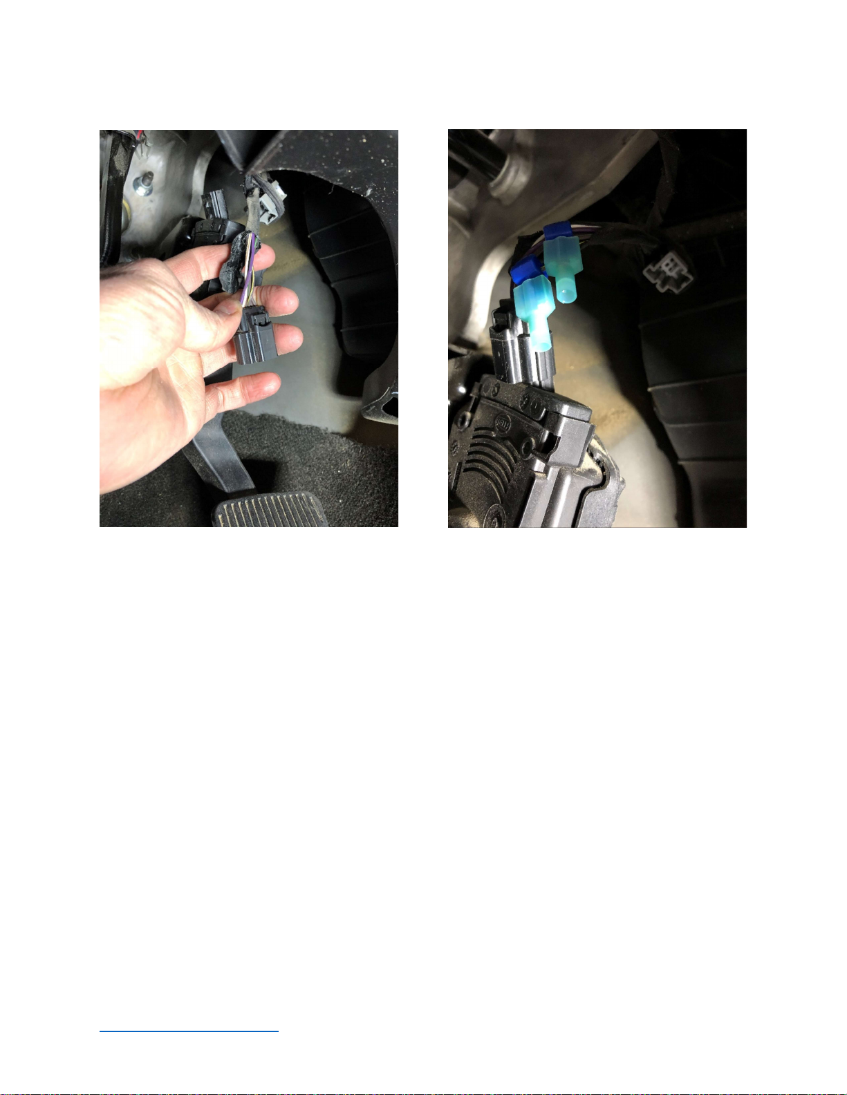
3. Locate the factory Accelerator Pedal Position (APP) plug located just above the
accelerator pedal. (See pictures )
4. Unplug the factory APP connector by pressing the release button.
5. Carefully peel back the protective sheathing to expose about 1½ inch of wires. If using a
razor blade be very careful to not cut into the insulation on the individual wires.
6. On the factory APP plug, locate the factory wire (see next page for wire identification),
and use the provided wire tap to crimp into that wire.
7. Connect the single wire labeled PIN 20 to the wire tap.
8. Plug the factory connector back into the APP plug.
9. When you’re done you should be able to unplug the opposite end of this PIN 20 wire
from our main wire harness and using a voltage probe detect approx. 0.4 volts from the
pedal at idle, and when depressed voltage should read 4.5 volts.
Page 9 of 25
Revision 2.6
Revision Date 6/7/2021 Turbonator® VGT Controller
www.dieselpowersource.com
APP Sensor Signal Wires
**Note: Although pictures show two connectors you will only tap one wire.**
2007.5-2009 | Brown/White Wire
2010-2012 | Brown/Light Green Wire
2013-2014 | Brown/Light Green Wire
2015-2018 | Brown/White Wire

Page 10 of 25
Revision 2.6
Revision Date 6/7/2021 Turbonator® VGT Controller
www.dieselpowersource.com
Exhaust Brake Wiring
12 Valve Cummins & Universal Kit
____________________________________________________________________________
Universal 2-wire kit can be used on 12 Valve non-electronic trucks. The 2 loose wires can be
shorted together to trigger the brake, after the brake switch is turned on.
To use with a micro-switch on 12V engines:
Do not connect these wires to anything but each other through a switch
The goal is for the pedal to close the circuit to engage the exhaust brake. You can verify the
pedal voltage in the software under Gauges / Voltages.
There are multiple ways you can do this
1. Attach a normally open, momentary microswitch, under your accelerator pedal. The
pedal must press on the switch when your foot is off the accelerator. Then release the
switch when your foot presses on the pedal.
2. Attach a microswitch to your injection pump, the injection pump must have a lever
attached to your accelerator pedal and must follow the same description as in option 1.
3. Attaching a momentary switch to your manual transmission shifter. Attaching
4. Set software to “Normally High” under the EXHAUST BRAKE tab
a. Set voltage to 7.0 v under the EXHAUST BRAKE tab as well.
Otros manuales para Turbonator VGT
1
Tabla de contenidos
Otros manuales de Controladores de DPS


