dormakaba 8600 EMR Installation Instructions
08281010 03-20208600 EMR 3
Technical specifications
1 Technical specifications
. Overview
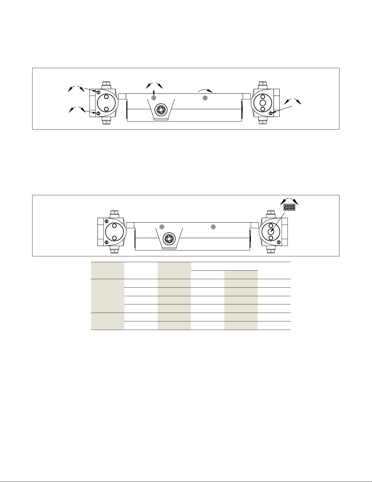
Each 8600 EMR series unit contains a door closer,
hold open electromagnet, and smoker detector. The
unit can be used as a single installation or as a
series of singles powered from one or more power
supplies. When a series of 8600 EMR units are
wired together in a run, groups of up to 5 units may
be interconnected. Interconnection is accomplished
through terminals #4 and #15 and results in all
units alarming when any one of them senses
smoke. In turn, all associated hold open
electromagnets are de-energized. Within any run of
detectored units, it is permissible to form as many
interconnected groups as the total power supply
amperage will allow; but, again no more than 5
units can be interconnected together.
. Preparation notes
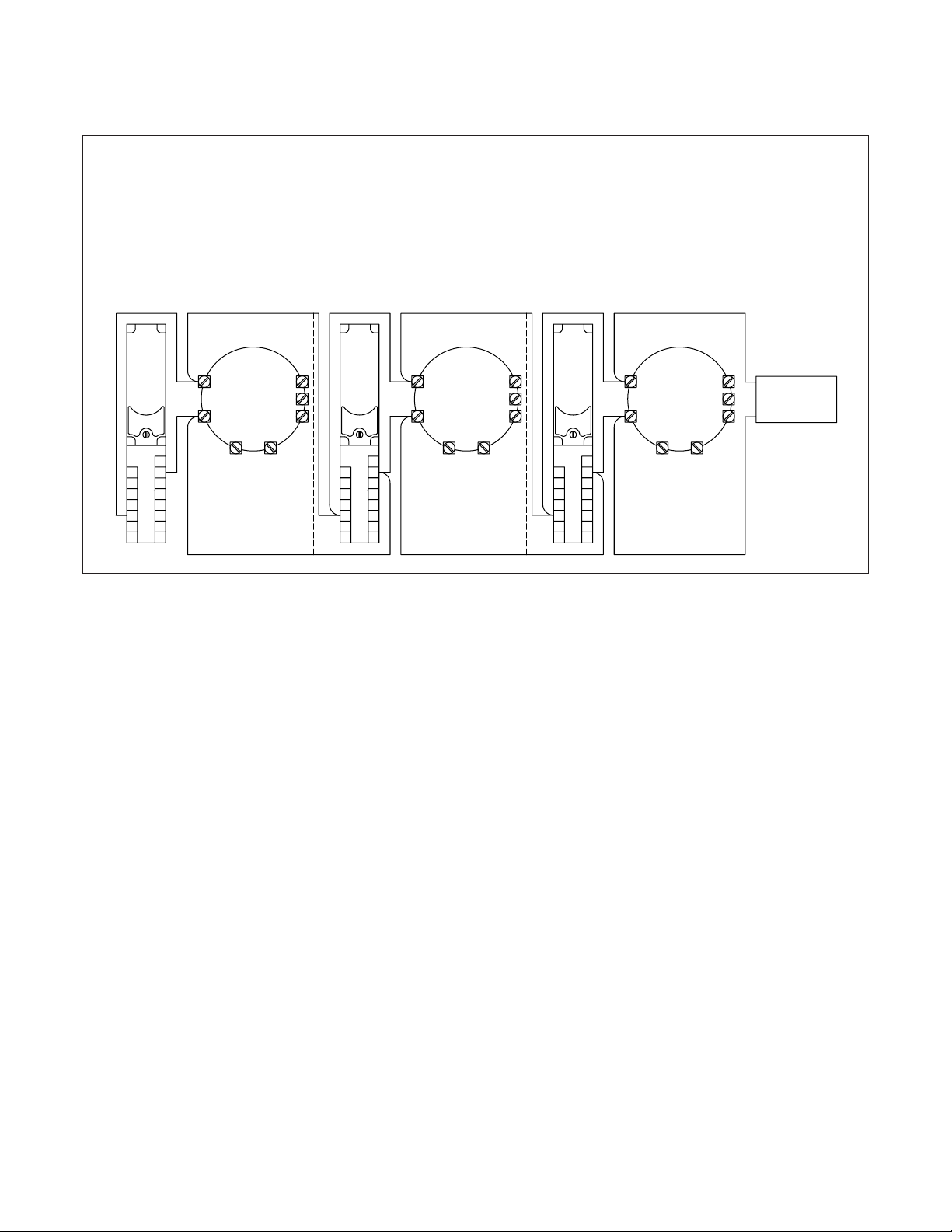
Any detectors 8600 EMR series unit can be
connected to an auxiliary EMF non-detectored unit,
or remote detector, or both. It can be a single
installation or part of any of the multiple
arrangements described above. An auxiliary unit
(double door applications) is a companion to the
main unit, and its electromagnet de-energizes
along with the main unit. A remote open area
detector sensing smoke alarms the 8600 EMR to
which it is connected and any other 8600 EMR to
which it is interconnected.
Single installations or groups of installations can
be connected to the alarm initiation circuit of a
compatible UL/ULC listed fire alarm control unit in
4-wire or 6-wire configurations.
Additional functions are provided to separately
power the hold open electromagnets directly from
the alarm control panel as well as connections for a
remote alarm indicator lamp.
1. Read entire instruction sheet prior to installation
and refere to NFPA 72E. Standards may be
obrained from THE NATIONAL PROTECTION
ASSOCIATION, Batterymarch Park, Quincy, MA
02269.
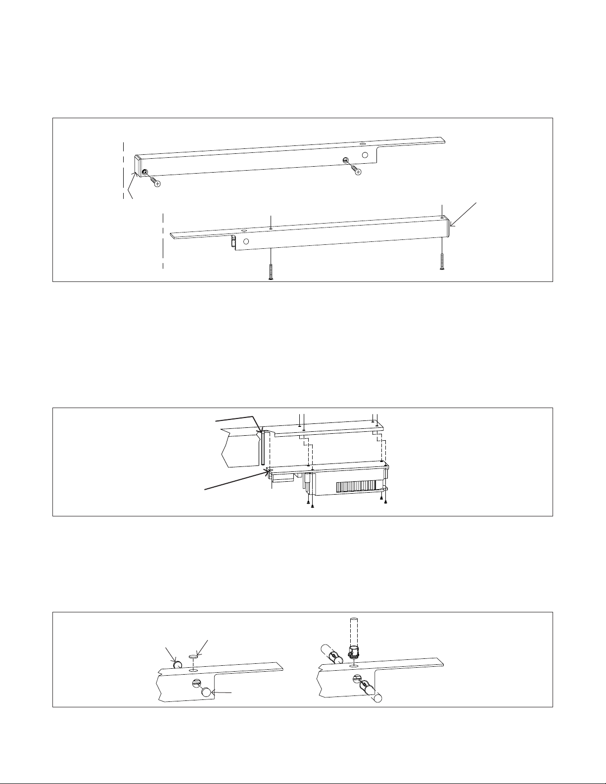
2. Reference unit carton for unit mounting type.
3. Prepare door and frame for fasteners using the
appropriate template. Mark, drill, and tap holes
as indicated. If surface wiring is used, omit 7/8”
hole for wire access.