DMM DYN 5 Series Manual de usuario

AC SERVO DRIVE
Modbus TCP/IP Specication
MANUAL CODE: DYN5-MBTCP-SL425-10A
REVISION: 10A
RELEASE DATE: October 2021
DYN
5
Series
This manual must be kept accessible for the user or operator.
Copyright © 2021 DMM Technology Corp.
Document Layout Dimension:
Letter 8.5 x 11inches (215.9 x 279.4 mm)

DYN5-MBTCP-SL425-10A PAGE 2 of 38
DMM TECHNOLOGY CORP.
DYN5 AC SERVO DRIVE
Modbus TCP/IP Specication
■ Safety Notice ■
The user or operator should read through this manual completely before installation, testing,
operation, or inspection of the equipment. The DYN5 series AC Servo Drive should be operated
under correct circumstances and conditions. Bodily harm or damage to equipment and system
may result if specications outlined in this document are not followed. Take extra precaution
when the above warning convention is used for certain critital specications.
■ Notations Used ■
Unless otherwise noted, all specication and units of measurement used in this manual are in
Metric standard units:
Mass: Kilogram [ kg ]
Length: Millimeter [ mm ]
Time: Seconds [ s ]
Temperature: Celsius [ °C ]
WARNING
!

DYN5-MBTCP-SL425-10A PAGE 3 of 38
DMM TECHNOLOGY CORP.
DYN5 AC SERVO DRIVE
Modbus TCP/IP Specication
Table of Contents
■ Safety Notice ■ 2
■ Notations Used ■ 2
Table of Contents 3
Section 1. Overview 4
Section 2. Network Connection 5
Section 3. Basic Setup Instructions 6
3.1 Servo Drive Setup 7
3.2 Ping (ICMP) Test 8
3.3 Modbus Poll Test 9
Section 4. Modbus Register Specifications 11
4.1 Modbus Register Overview 11
4.2 Modbus Register Outline 12
4.3 Modbus Register Details 13
Section 5. PLC Communication Example 22
5.1 Initial Communication - Read from register 0xFFFE Diagnostic Counter 23
5.2 Speed Command and Speed Feedback Example 25
5.3 Profile Relative Position Command Example 28
Section 6. Servo Drive Communication Response Time 31
Appendix A - DMMDRV5 Communication Setup 32
Appendix B - Profile Position Command Trajectory Calculator 33
Appendix C - DTPU Dynamic Target Position Update Specification 34
Warranty and Liability 36
Manual Disclaimer 37
Manual Revisions 37
DYN5-MBTCP-SL425-10A PAGE 4 of 38
DMM TECHNOLOGY CORP.
DYN5 AC SERVO DRIVE
Modbus TCP/IP Specication
Section 1. Overview
The DYN5 servo drive optioned with Modbus TCP/IP communication allows the servo drive to
be fully operated on a Modbus TCP/IP network. The DYN5 servo drive acts as Server (Slave)
device and exchanges data with a Client (Master) device. Through this network, the Client has
full access and control of the servo drive including:
• Reading and Writing servo drive parameters
• Reading servo motor Position/Speed/Current/Torque
• Reading servo drive Status
• Sending Position/Speed/Torque command
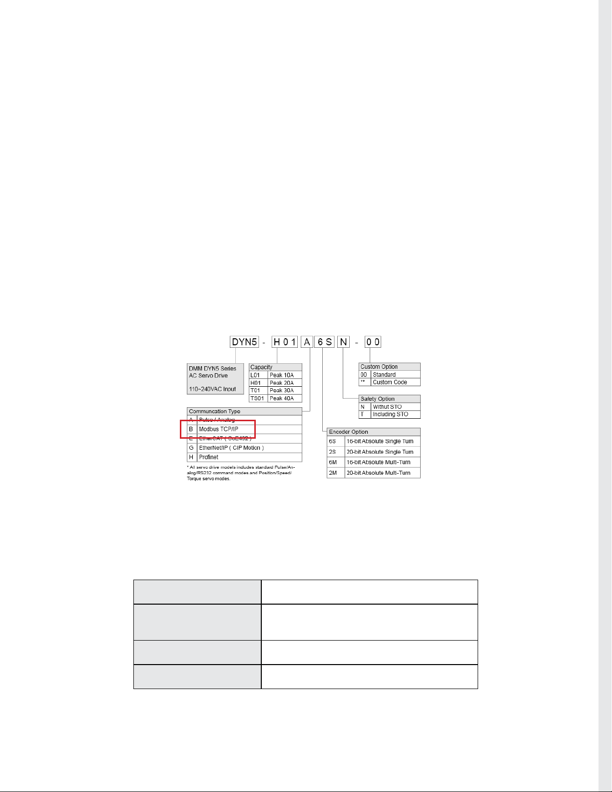
♦ Compatible Model Numbers
The DYN5 servo drive with the below model numbers are optioned with Modbus TCP/IP com-
munication. Note that the servo drive optioned with Modbus TCP/IP still has base Pulse/Analog/
RS232 capability it the user wishes to use these control methods.
For additional infomration regarding Modbus TCP/IP network and protocol specication, please
refer to Modbus Organization at www.modbus.org.
♦ Basic Specication
Interface 10/100 Base-T Ethernet IEEE 802.3
Hardware Interface RJ45 Recommended CAT5 or higher cable with
braid shielding
Communication Speed 10/100 Mbps - Drive Auto Detect
IP Addressing Static – Set in DMMDRV5 program

DYN5-MBTCP-SL425-10A PAGE 5 of 38
DMM TECHNOLOGY CORP.
DYN5 AC SERVO DRIVE
Modbus TCP/IP Specication
Section 2. Network Connection
For general DYN5 servo drive operation and wiring instructions, refer to DYN5 servo drive in-
struction manual Manual# DYN5MS-ZM1.
Connector JP5A and JP5B are used for the Modbus TCP/IP interface. Both connectors are stan-
dard RJ45.
The DYN5 servo drive supports daisy-chain topology, JP5A is used for input, JP5B is used for
output. The last servo drive on the chain should have JP5B terminated with the JP5 Terminator
(Part# CN5-JP5-TMD1). If only 1 servo drive is on the network, the terminator still needs to be
connected to JP5B, with JP5A connected to the Client (Master).
♦ Part# CN5-JP5-TMD1 - DYN5 JP5 Ethernet Network End Terminator
♦ Single Servo Drive Network Connection
♦ Multiple Servo Drive Network Connection
Modbus TCP Client
PLC, PC etc.
Ethernet Cable
Connect Ethernet Network
End Terminator to JP5B
Connect controller to JP5A
Modbus TCP Client
PLC, PC etc.
Connect controller to rst
servo drive JP5A
Connect Ethernet Network End Terminator to last
servo drive JP5B
Connect rst servo drive
JP5B to second servo drive
JP5A
Connect additional servo
drive from JP5B to JP5A

DYN5-MBTCP-SL425-10A PAGE 6 of 38
DMM TECHNOLOGY CORP.
DYN5 AC SERVO DRIVE
Modbus TCP/IP Specication
Section 3. Basic Setup Instructions
Follow below instructions to setup a Modbus TCP/IP communication between the DYN5 servo
drive and a PC Modbus TCP/IP Client. These instructions are the same for all DYN5 servo drive
models with Modbus TCP/IP option.
For general DYN5 servo drive operation and wiring instructions, refer to DYN5 servo drive in-
struction manual Manual# DYN5MS-ZM1.
(A) Wiring and Connections
Follow below diagram for basic minimum wiring for Modbus TCP/IP communication testing. Note
the below diagram does not include any reference for EMI, grounding or safety. Refer to DYN5
servo drive instruction manual for these considerations.
JP5A Modbus TCP/IP Client PC
(Modbus Poll software)
Connect Ethernet Network
End Terminator to JP5B
T2 Connect to servo motor
power via motor power
cable
D2
D1
Short D1/D2
L2
L1
R
T
S
JP2 Connect to PC DMMDRV5
software via USB Cable
(DMM Part# CA-DYN5USB-FR3)
T3 Power logic L1/L2
and control R/S/T with
110~220VAC
JP3 Connect to servo motor
encoder feedback cable
(B) Parts Needed
• DYN5 AC Servo Drive with Modbus TCP/IP option
• DXT/DST/DHT AC Servo Motor
• Encoder Feedback Cable to connect servo motor to servo drive
• Motor Power Cable to connect servo motor to servo drive
• Mini-USB to USB-A cable to connect servo drive to PC DMMDRV5 software
(DMM Part# CA-DYN5USB-FR3)
• Ethernet cable to connect servo drive JP5A to PC for Modbus TCP/IP communication
• Part# CN5-JP5-TMD1 - DYN5 JP5 Ethernet Network End Terminator
• PC computer with DMMMDRV5 software
• PC computer with Modbus Poll software (www.modbustools.com)
* Note all ethernet cables used should be Straight Through type and not Crossover type cables
DYN5-MBTCP-SL425-10A PAGE 7 of 38
DMM TECHNOLOGY CORP.
DYN5 AC SERVO DRIVE
Modbus TCP/IP Specication
(1) Download and install DMMDRV5 software.
(2) Download and install Modbus Poll software (www.modbustools.com). Modbus Poll is a Mod-
bus TCP/IP master (Client) simulator software for PC computer.
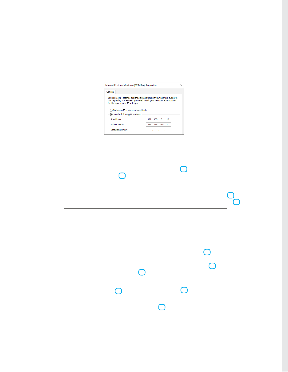
(3) Check PC ethernet port TCP/IPv4 settings. This is needed to set and match with the servo
drive IP address. For this example, the PC IP address is set to 192.168.0.10 and subnet mask
255.255.255.0
(4) Connect all components to servo drive as above diagram (A) Wiring and Connections. Apply
power to servo drive.
(5) Establish connection between DMMDRV5 program and DYN5 servo drive. See Appendix A
for connection setup instructions.
(6) Open the Servo Setting module. Select Position Servo Mode 1 . Select Ethernet Com-
mand Input Mode (Modbus TCP/IP) 2 . Note no matter the operation command from Modbus
TCP/IP, the servo drive should be set into Position Sero Mode here. The servo drive will internal-
ly switch between Position/Speed/Torque servo modes according to the command received from
Modbus TCP/IP. Set the servo drive IP address within the network of the PC IP address 3 . In
this example, the servo drive IP address is set to 192.168.0.20. Set GEAR_NUM to 16384 4 .
(7) Click Save All to save new settings into servo drive 5 . Power cycle servo drive - remove
power from both L1/L2 and R/S/T. Wait 30 seconds, then apply power again.
The DYN5 servo drive is now correctly setup for Modbus TCP/IP.
1
2
3
5
3.1 Servo Drive Setup
4

DYN5-MBTCP-SL425-10A PAGE 8 of 38
DMM TECHNOLOGY CORP.
DYN5 AC SERVO DRIVE
Modbus TCP/IP Specication
Check servo drive ethernet connectivity using Ping test on PC.
(1) Open the PC Command Prompt.
(2) Type “ping AAA.AAA.AAA.AAA” where AAA.AAA.AAA.AAA is the servo drive IP address set
in Section 3.1 Step. 6.
(3) Check that a reply is received back from the servo drive. This conrms the servo drive is in
Ethernet mode and IP address is set correctly.
(4) If reply is not received from servo drive, check all connections and settings in Section 3.1.
3.2 Ping (ICMP) Test

DYN5-MBTCP-SL425-10A PAGE 9 of 38
DMM TECHNOLOGY CORP.
DYN5 AC SERVO DRIVE
Modbus TCP/IP Specication
Check Modbus TCP/IP connectivity using Modbus Poll software. Modbus Poll software turns the
PC into Modbus Client (master) used to test servo drive communication.
(1) Open the Modbus Poll software.
(2) Click Connection->Connect. Select Modbus TCP/IP connection. Input servo drive IP ad-
dress. Make sure server port is set to 502 for standard Modbus TCP port. Make sure IP protocol
is set to IPV4. Click OK. Check that connection is established and registers are read from servo
drive.
3.3 Modbus Poll Test
192.168.0.20
(4) See Section 4. for servo drive Modbus Register specication. The default Modbus Poll pro-
gram reads 10 registers from address 0x00 to 0x09. The registers are read once a second and
the “Tx” counter on top increments each time a read is successful.

DYN5-MBTCP-SL425-10A PAGE 10 of 38
DMM TECHNOLOGY CORP.
DYN5 AC SERVO DRIVE
Modbus TCP/IP Specication
(6) Select both 0x1D and 0x1E register displays and right click, select Format->32-bit signed-
>big endian. This will automatically combine the two 16-bit Modbus registers into one 32-bit
signed data showing full motor position on 0x1D display location. The position displayed should
be 0 or close to 0 as the motor position drifts slightly at steady state 1 . If the servo drive is set
to Absolute mode, the readout position will be single-turn or multi-turn absolute position.
(7) Recall in Section 3.1, Step 6, GEAR_NUM parameter was set to to 16384. This sets the
position command ratio so that a prole position command of 65536 will move the motor 1 revo-
lution (for motors equipped with 16-bit resolution encoders). See Appendix B for Prole Position
Command trajectory details.
(8) Send a command to move the motor 1 revolution. Select Functions->16 Write Registers.
Relative Prole position command is register 0x17 and 0x18.
(9) Set to settings as below and Click Send to send a position command of 65536 and check that
the motor moves exactly 1 revolution Clockwise. The position readout from 0x0D (Step 6) should
now read 65536 to indicate the motor has rotated exactly 1 revolution.
(5) (Relative Prole Position command example) Set Modbus Poll so it reads from register
containing servo motor position. Click Setup->Read/Write Denition. 32-bit servo motor position
is contained in registers 0x1D and 0x1E. Set to below setting and click OK. Note Slave ID
number does not matter.
Step 5
Step 6
1
Otros manuales para DYN 5 Series
2
Tabla de contenidos
Otros manuales de Servoaccionamiento de DMM


Manuales populares de Servoaccionamiento de otras marcas

Mitsubishi Electric
Mitsubishi Electric MELSERVO-J5 MR-J5-G Series Manual de usuario

Robotis
Robotis XH430-W350-T Manual de usuario

NTI AG
NTI AG LinMot C1250 Series Manual de usuario

Welcon
Welcon WE2A D048 Series Manual de usuario

Parallax
Parallax 900-00005 Manual de usuario

Festo
Festo TP 1410 Manual de usuario


