Digitus Biometrics dbServerRackV2 Zero-U Guía

db ServerRack V2 (Zero-U)
Installation Manual

Model: db ServerRack V2 Zero-U Digitus Biometrics, Inc. 2011
Page 2 of 24
Table of Contents
Determining which Lock Pawl to use................................................................................................3
Mounting the Door Interface Box ...................................................................................................5
Mounting the Door Interface Box - Step 1 .........................................................................................5
Mounting the Door Interface Box – Step 2 .........................................................................................6
Mounting the Door Interface Box – Step 3 .........................................................................................7
Mounting the Door Interface Box - Step 4 .........................................................................................8
Mounting the Door Interface Box - Step 5 .........................................................................................9
Mount the Tie Down Pads to the Door and Cabinet ............................................................................ 10
Connect the CAT5 Cable to the Control Unit..................................................................................... 12
Installing the Pawl on the Door Lock.............................................................................................. 14
Using the Tamper Switch Inputs ................................................................................................... 15
Using the Door Contact Inputs..................................................................................................... 17
Using the Alarm Output ............................................................................................................ 19
Using the Wiegand Output......................................................................................................... 20
Using the Door 2 Output ........................................................................................................... 21
Install the 2nd BioLock (Option I)................................................................................................... 21
Install the Electro-Mechanical Lock (Option II)................................................................................... 21
Connecting Power to the Control Unit............................................................................................ 23

Model: db ServerRack V2 Zero-U Digitus Biometrics, Inc. 2011
Page 3 of 24
Determining which Lock Pawl to use
•As all cabinets vary, we offer a wide range to pawls to suit the particular dimensions of your cabinet.
•There are 2 simple measurements that need to be taken to determine which pawl you will need.
•Please obtain the measurements as show in Figure 1 and Figure 2 and contact our electromechanical lock support
team as show below:
Southco Global Cor
p
orate Head
q
uarters
Customer Service & Technical Support
Ctr.
Concordville, PA – US
A
Tel:
(610) 459-4000
Email: [email protected]
Figure 1 Figure 2

Model: db ServerRack V2 Zero-U Digitus Biometrics, Inc. 2011
Page 4 of 24
Mounting the Control Unit
•Mount the db ServerRack v2 Zero-U Control Unit
oThe Control Unit can be attached using the Magnetic Strips for Steel Cabinets or VHB Strips for Aluminum
Cabinets.
oAlternatively, the Control Unit can be placed on a cabinet shelf
•It is preferable to mount the Control Unit near the top of the rack, to ease the running of cables, however this isn't
absolutely necessary.
Figure 3

Model: db ServerRack V2 Zero-U Digitus Biometrics, Inc. 2011
Page 5 of 24
Mounting the Door Interface Box
•If you are installing the db ServerRack Access Control unit to a cabinet that already has a lock installed, remove the
existing lock at this time.
•The "Door Interface Box" provides an interface between the Control Unit and the fingerprint scanner. It also provides
all power and signal connections to the electric lock.
•Install the Door Interface Box as show in Figures 4 thru 9.
Mounting the Door Interface Box - Step 1
•Before removing the double-sided high bond tape from the Door Interface Box, find a suitable location on the inside
of the cabinet door to mount Interface Box.
•Ensure that the selected location will not affect the cabinet door from closing correctly.
•Note that for glass paneled cabinet doors with very narrow frames, the only suitable location may be on the glass.
IMPORTANT:
•Ensure that the Interface Box is located close enough to the lock opening in the door, so that the finger-
sensor on the ribbon cable can go through the door and connect into the lock, see Figure 6.
•Once you have found a suitable location where you intend to mount the Door Interface Box, ensure that the door
surface is clean and free from any debris. (Using neat alcohol to clean the surface is highly recommended. Allow
drying time before proceeding.)
•Remove the protective cover from the double-sided high bond tape located along the edge of the Door Interface
Box.
Figure4

Model: db ServerRack V2 Zero-U Digitus Biometrics, Inc. 2011
Page 6 of 24
Mounting the Door Interface Box – Step 2
•Attach the Door Interface Box to the inside door surface. Only apply a slight amount of pressure to the high bond
tape until you have ensured that the Door Interface Box will not prevent the cabinet door from closing.
•Once you have ensured that the door will close properly and the finger sensor can attach to the lock, apply more
pressure to the high bond tape. The more pressure applied, the greater the bond.
Figure 5
* Open slot for lock. 25mm x 150mm (typical)
IMPORTANT:
Ensure that the Interface Box is located
close enough to the lock opening in the
door, so that the finger-sensor on the
ribbon cable can go through the door
andconnectintothelock,seeFigure6.

Model: db ServerRack V2 Zero-U Digitus Biometrics, Inc. 2011
Page 7 of 24
Mounting the Door Interface Box – Step 3
•Push the finger-sensor assembly through the door lock opening as shown in Figure 6.
•Attach the finger-sensor assembly into the back of the door lock as show in Figure 7. Ensure that the angle of the
finger-sensor assembly and the angle of the door lock are as shown in Figure 7.
Figure 6 Figure 7

Model: db ServerRack V2 Zero-U Digitus Biometrics, Inc. 2011
Page 8 of 24
Mounting the Door Interface Box - Step 4
•Situate the lock on the outside of the cabinet door, so that the ribbon cable attached to the finger-sensor assembly
is at the top of the locking opening. (See Figure 8)
Figure 8

Model: db ServerRack V2 Zero-U Digitus Biometrics, Inc. 2011
Page 9 of 24
Mounting the Door Interface Box - Step 5
•Secure the lock to the door using the Top Mounting Bracket and Bottom Mounting Bracket as show in Figure 9. Do
not over-tighten the screws in the Bottom Mounting Bracket as this may jam the lock mechanism.
•Attach the lock wire coming out of the Door Interface Box to the back of the lock as shown in Figure 8. The wire will
only plug in one way.
Figure 9
Model: db ServerRack V2 Zero-U Digitus Biometrics, Inc. 2011
Page 10 of 24
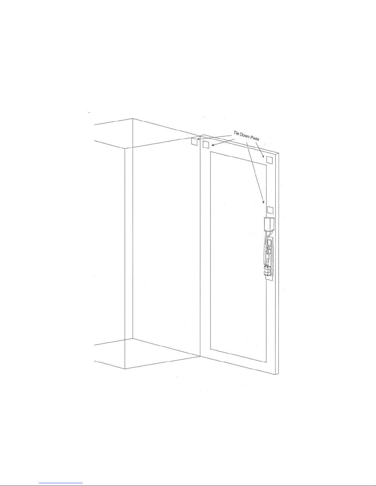
Mount the Tie Down Pads to the Door and Cabinet
•The Tie Down Pads are used to secure the CAT5 cable that connects the Door Interface Box to the Control Unit.
•Ensure that the door surface is clean and free from any debris. (Using neat alcohol to clean the surface is highly
recommended. Allow drying time before proceeding.)
•Remove the protective cover from each Tie Down Pad and situate as shown in Figure 10.
Figure 10
Tabla de contenidos


