6 EVOLUTION 1 SYSTEM MANUAL Issue 1.1 20 Dec 2006
INSTALLATION AND OPERATION MANUAL
PART 1: INSTALLATION PROCEDURES
INSTALLING THE EVOLUTION II PRINTING SYSTEM
Caution should be taken while installing the EVOLUTION printing system on your
equipment. Digital Design Inc. has taken every precaution to ensure a safe and
accurate instruction set to guide the installer through the installation process.
Follow the operational guidelines in the installation procedures.
VERIFY THAT YOUR EQUIPMENT IS IN PROPER OPERATING
CONDITION.
LOCATE A CONVENIENT POSITION ON YOUR EQUIPMENT.
EVOLUTION II REQUIRES 4-1/2" OF SPACE ON THE PRODUCTION
LINE.
FOLLOW THE INSTALLATION PROCEDURES.
READ CAREFULLY ALL INSTALLATION PROCEDURES BEFORE
PROCEEDING.
INSTALL THE PRINTING SYSTEM ON YOUR EQUIPMENT.
THERE IS NO EXTRA HARDWARE REQUIRED OTHER THEN
THAT SUPPLIED IN THE INSTALLATION KIT.
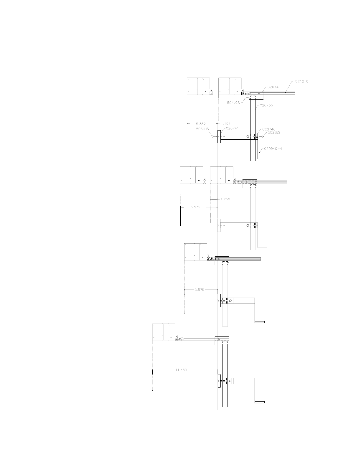
MOUNTING ON PRODUCTION LINE
Locate the supplied mounting template
and affix in a convenient location on the
production line. Spot and drill both
mounting holes for a 5/16” bolt. NOTE:
the user may also thread the side of the
conveyer using a 5/16” tap.
Fasten the mounting bracket to the
conveyer using the supplied mounting
hardware and ensuring that the supplied
ground strap is located securely beneath
either of the two mounting bolts, and that
conductivity to earth ground is less than 1 ohm. This ensures a proper path for
static discharge, should the need arise.