
Digiplex DGP-319 Instrucciones de montaje

16-Zone and 16-Remote Wireless Bus Module
V1.3
DGP-319
Installer’s Guide


TABLE OF CONTENTS
1.0 INTRODUCTION .............................................................................. 3
1.1 Technical Specifications .........................................................................3
1.2 System Features .....................................................................................3
2.0 INSTALLATION ............................................................................... 4
2.1 Location ..................................................................................................4
2.2 Connections and Mounting .....................................................................4
3.0 PROGRAMMING ............................................................................. 6
3.1 Programming Methods ............................................................................6
3.2 Low Battery Supervision .........................................................................7
3.3 Check-in Supervision ..............................................................................8
3.4 Tamper Supervision on Receiver Module ...............................................8
3.5 PGM Deactivation Mode .........................................................................9
3.6 PGM Base Time ......................................................................................9
3.7 PGM Timers ............................................................................................9
3.8 PGM Activation Event .............................................................................10
3.9 PGM Deactivation Event .........................................................................11
3.10 PGM Override .......................................................................................11
3.11 System Reset .......................................................................................12
3.12 Viewing Unknown Serial Numbers ........................................................12
4.0 DETECTORS AND CONTACT SWITCHES .................................... 13
4.1 Assigning Detectors & Contact Switches to Receiver .............................13
4.2 Assigning Detectors & Contact Switches to Zones .................................14
4.3 Viewing Signal Strength of Detectors & Contact Switches .....................14
5.0 REMOTE CONTROLS ..................................................................... 16
5.1 Assigning Remote Controls to the Receiver Module ..............................16
5.2 Assigning Remote Controls to User Access Codes ................................17
5.3 Programming Remote Control Buttons ...................................................18
5.4 Replacing the Remote Control’s Battery .................................................22

2 Installer’s Guide

Digiplex Liberator 3
1.0 INTRODUCTION
1.1 TECHNICALSPECIFICATIONS
Manchester Decoding
Diversity Antenna
Error Detection & Correction
Frequency Hopping: @ 902 MHz - 928 MHz or 868MHz
Range: Detectors & Contact Switches:
1000m (3280ft) or 300m (984ft) for 868 MHz
Remote Controls: 30m (100ft)
Sensitivity: -105dBm
Current Consumption: 70 mA
Dimension (without antennas) 15cm H x 16cm L x 3cm W
(6in H x 6.5in L x 1.1in W)
Operating Temperature: 0°C to 50°C (32°F to 122°F)
Operating Humidity: 85%
PGM Outputs: 1 relay (an additional PGM Output is available)
PGM Output current: 5A
1.2 SYSTEMFEATURES
Add 16 wireless detectors or contact switches to the Digiplex System
Add 16 remote controls to the Digiplex System
Reflow Design
No tuned Circuit
Tamper Switch
Low Battery, Check-in, and Tamper supervision through Digiplex Control Panel
Trouble Display through Digiplex Control Panel
Signal Strength Indicator

4 Installer’s Guide
2.0 INSTALLATION
2.1 LOCATION
Mount the Wireless Bus Module on a wall allowing at least 5cm (2ft) around the
module to permit adequate ventilation and heat dissipation. Select a site that is not
susceptible to drastic temperature changes. Avoid installation near or in the path of
strong RF fields (i.e. neon lights, computers), on or near metal objects, circuit
breaker boxes, air conditioners, and heater ducts since they may cause interference
and reduce its sensitivity. We recommend installing it in a centralized location on the
main floor. Avoid installing it in the basement. Refer to the Digiplex Control Panel's
Reference & Installation Manual for maximum allowable distances between the
control panel and the Wireless Bus Module.
2.2 CONNECTIONSAND MOUNTING
Firmly screw the two antennas into the connectors marked ANT on the Receiver
Module (see Figure 2.1). Using a drill or screwdriver, punch out the four mounting
holes on the back of the plastic case. Align the six holes of the printed circuit board
with the six pins on the back plastic mounting case and snap into place. If placed
correctly, the antennas will lean directly over the grooves in the mounting case.
Do not cut, bend, or alter the antennas. Avoid mounting the Receiver
Module near or on metal as this may affect its sensitivity.
The Wireless Bus Module is connected to the control panel's bus in a star and/or
daisy chain configuration. The bus is a 4-wire communication bus that provides
power and two-way communication between the control panel and all the modules
connected to it. Connect the GRN and YELterminals from the Receiver Module to the
corresponding GRN and YELterminals of the control panel. Connect the REDterminal
to the AUX+ of the control panel. Connect the BLKterminal to the AUX- of the control
panel.
Remove AC power and then remove the battery from the control panel
before adding a bus module to the system or it may cause communication
trouble.

Digiplex Liberator 5
Figure 2.1: Connections for Receiver Module to Control Panel
6 Installer’s Guide
3.0 PROGRAMMING
3.1 PROGRAMMINGMETHODS
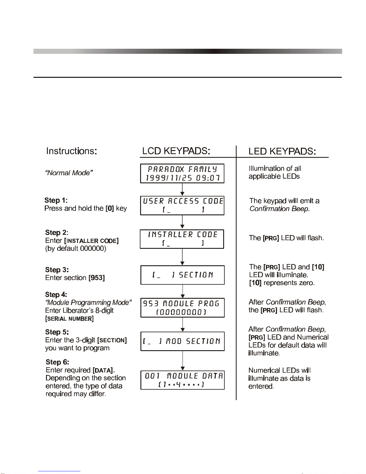
All programming can be done through Module Programming Mode in the Digiplex
Control Panel from any keypad as shown in Figure 3.1. The sections referred to in
Step 5 and the data referred to in Step 6 from Figure 3.1 are explored in the
following sections of the manual.
Figure 3.1: Module Programming Mode

Digiplex Liberator 7
3.1.1 Feature Select Programming
Sections [001], [002] and PGM Programming are programmed using the Feature Select
Method, where each number from 1 to 8 corresponds to a specific feature or option. Set
these options by turning the number corresponding to the feature ON or OFF. The option
is considered ON when the number appears within the brackets on the LCD keypad or
when the number is illuminated on an LED Keypad. Press the key again to remove or
extinguish the digit, thereby disabling (turning OFF) the option. You turn options ON and
OFF by pressing the corresponding keys on the keypad. Press the keys as many times
as you need to select the desired options and then press [ENTER]to save.
3.1.2 Module Broadcast
Copy sections [001] to [008] of one Wireless Bus Module to one or more Wireless Bus
Modules. For details see the Digiplex Reference & Installation Manual.
3.1.3 WinLoad
With the WinLoad Security System Management Software, the control panels, modules
and keypads can be programmed remotely through a modem or on-site at 19,200 baud
with a 306 Adapter. For details refer to the Digiplex Reference & Installation Manual.
3.2 LOWBATTERYSUPERVISION
SECTION[001]: OPTION[1]
When a detector or contact switch’s battery voltage drops below a recommended
level (refer to the transmitter’s Instruction Sheet), its yellow LED will flash and it will
transmit a signal to the Wireless Bus Module indicating that the voltage is low. If this
option is enabled, the Receiver Module will transmit the signal to the control panel.
The control panel will generate a trouble and can transmit a report code to the
monitoring station. For details refer to the Digiplex Reference & Installation Manual.
From Step 6 in Figure 3.1, page6, enable or disable the option:
Option [1] OFF = Low Battery Supervision disabled
Option [1] ON = Low Battery Supervision enabled (default)

8 Installer’s Guide
3.3 CHECK-INSUPERVISION
SECTION[001]: OPTIONS[2] AND[3]
The Wireless Bus Module waits for each of its assigned detectors and/or contact
switches to send a status signal within a specified time period to confirm their
presence and functionality. If a device has not sent a signal within the time period,
the Wireless Bus Module will transmit a supervision loss signal to the control panel.
The control panel can generate a trouble, an alarm and/or can transmit a report
code to the monitoring station. For details refer to the Digiplex Reference &
Installation Manual. Option [2] enables the Check-in Supervision feature and option
[3] specifies the time period required for the devices to send their signal.
From Step 6 in Figure 3.1, page6, enable or disable the options:
Option [2] OFF = Check-in Supervision disabled
Option [2] ON = Check-in Supervision enabled (default)
Option [3] OFF = Check-in every 12 hours (default)
Option [3] ON = Check-in every 12 minutes
Ensure that the assigned detectors and/or contact switches are set to the
same time period as the Receiver Module (i.e. if the Receiver Module is set
to Check-in every 12 minutes, the detectors/contact switches must be set to
Check-in every 12 minutes.
3.4 TAMPERSUPERVISIONONRECEIVERMODULE
SECTION[001]: OPTION[4]
If this option is enabled and the Receiver Module's cover is removed, the on-board
tamper switch will be triggered. When this occurs, the Wireless Bus Module will
transmit a tamper signal to the control panel. The control panel can generate a
trouble, an alarm and/or can transmit a report code to the monitoring station. For
details refer to the Digiplex Reference & Installation Manual.
From Step 6 in Figure 3.1, page6, enable or disable the option:
Option [4] OFF = Receiver Module's Tamper Supervision disabled (default)
Option [4] ON = Receiver Module's Tamper Supervision enabled
Tabla de contenidos


