DiBoss LT-32HTFH Manual de usuario

SERVICE MANUAL
COLOR TFT-LCD TV
SERVICE MANUAL
MODEL :LT-32HTFH
CAUTION !!
BEFORESERVICINGTHETFT-LCDTV,
READTHE SAFETY PRECAUTIONS IN THIS MANUAL.

SERVICE MANUAL
CONTENTS
Contents ------------------------------------------------------------------------- 2
Safety precautions ----------------------------------------------------------- 3
Servicing precautions ------------------------------------------------------- 4
Specifications ------------------------------------------------------------------ 5
Location of control ----------------------------------------------------------- 9
Trouble Shooting ------------------------------------------------------------- 12
Deassembly procedure ---------------------------------------------------- 14
Exploded Drawing ----------------------------------------------------------- 19
Wire dressing ------------------------------------------------------------------ 20
Adjustment instruction with Default FactoryData----------------- 21
Inspection instruction ------------------------------------------------------ 23
PCB Layout --------------------------------------------------------------------- 26
Schematic Diagram -----------------------------------------------------------31
Replacement part list -------------------------------------------------------- 32
Block Diagram ----------------------------------------------------------------- 33
Circuit descriptions ---------------------------------------------------------- 34

SERVICE MANUAL
SAFETY PRECAUTIONS
Leakage Current Hot Check (See below Figure)
Plug the AC cord directly into the AC outlet.
Do not use a line Isolation Transformer during this check.
Connect 1.5K/10watt resistor in parallel with a 0.15uF capacitor between a known good earth
ground (Water Pipe, Conduit, etc.) and the exposed metallic parts.
Measure the AC voltage across the resistor using AC voltmeter with 1000 ohms/volt or more
sensitivity.
Reverse plug of the AC cord into the AC outlet and repeat AC voltage measurements for each
exposed metallic part. Any voltage measured must not exceed 0.75 volt RMS, which is,
corresponds to 0.5mA.
In case any measurement is out of the limits specified, there is possibility of shock hazard and
the set must be checked and repaired before it is returned to the customer.
Leakage Current Hot Check circuit
!! Important Safety Notice !!
Many electrical and mechanical parts in this chassis have special safety-related
characteristics.
These parts are identified by in the Schematic Diagram and Replacement Parts List.
It is essential that these special safety parts should be replaced with the same components
as recommended in this manual to prevent Shock, Fire, or other Hazards.
Do not modify the original design without permission of manufacturer.

SERVICE MANUAL
SERVICING PRECAUTIONS
CAUTION!!
Before servicing receivers covered by this service manual, read and follow the SAFETY
PRECAUTIONS on page 2 of this publication.
General Servicing Precautions
1.Always unplug the receiver AC power cord from AC power source before;
ⓐRemoving or reinstalling any component, circuit board module or any other receiver assembly.
ⓑDisconnecting or reconnecting any receiver electrical plug or other electrical connection.
ⓒConnecting a test substitute in parallel with an electrolytic capacitor in the receiver.
CAUTION!! A wrong part substitution or incorrect polarity installation of electrolytic capacitors
may result in an explosion harzard.
2.Do not spray chemicals on or near this receiver or any of its assemblies.
3.Do not defect any plug/socket voltage interlocks with which receivers covered by this service
manual might be equipped.
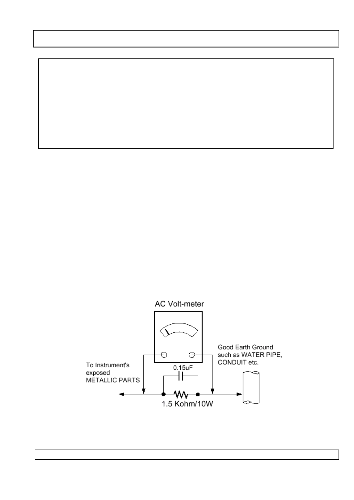
4.Always connect the test receiver ground lead to the receiver chassis ground before
connecting the test receiver positive lead. Always remove the test receiver ground lead last.
5.Do not connect the test fixture ground strap to power supply heatsink in this receiver
Electrostatically Sensitive(ES) Devices
Some semiconductor(solid state) devices can be damaged easily by static electricity. Such
components commonly are called Electrostatically Sensitive(ES) Device.Examples
Circuit Board Foil Repair
Excessive heat applied to the copper foil of any printed circuit board will weaken the adhesive
that bonds the foil to the circuit board causing the foil th separate from or “lift-off” the board.
The following guidelines and procedures should be flollowed whenever this condition is
encountered.
At IC Connections
To repair a defective copper pattern at IC connections use the following procedure to install a
jumper wire on the copper pattern side of the circuit board.(Use this technique only on IC
connections.)
1.Carefully remove the damaged copper pattern with a sharp knife.
(Remove only as much copper as absolutely necessary.)
2.Carefully scratch away the solder resist and acrylic coating(if used) from the end of the
remaining coopper pattern.
3.Bend a small “U” in one end of a small guage jumper wire and carefully crimp it around the
IC pin.
4.Route the jumper wire along the path of the out-away copper pattern and let it overlap the
previously scraped end of the good copper pattern. Solder the overlapped area and clip off
any excess jumper wire.

SERVICE MANUAL
SPECIFICATIONS
Note: Specifications and others are subject to change without notice for improvement.
1.Scope.
This document is the specification of 32” TFT-LCD Color TV.
2.Power
1) Power requirement
150W
2) AC / DC SMPS.
Input Frequency : 50 / 60㎐
Input Voltage: AC 100V- 240V 2.5A ~1.5A
Output Voltage: DC 12V, 24V
3) Power cord
Use UL listed and CSA certified detachable power cord type; SVT, 3-conductors, 18AWG
For AC 120V area. Use VDE listed detachable power cord type; HO5VV-F, 3-conductors,
18AWG for AC 220 240V area.~
3.Tuning system
FVS 100 Program
4.Sound output
10W+10Wrms Stereo (Max)
5.Antenna input impedance
VHF / UHF at 75ohm
6.OSD Type (On Screen Display)
Windows type (Center)
7.External in/output
HDMI INPUT, PC ANALOG INPUT, PC AUDIO INPUT, HEADPHONE OUTPUT, SVC port
S-VIDEO AUDIO INPUT, S-VIDEO INPUT, COMPONEN INPUT, COAXIAL OUT,
SCART 1(FULL), SCART 2(HALF), TUNER
8. Function
CATV/Hyper band
Auto Program
Manual Program
Auto Sleep
Quick view
ACMS(Auto channel Memory System)
PSM(Picture Status memory)
SSM(Sound Status memory)
PIP :COMPONET, PC-ANALOG, HDMI(Main) – Tuner, SCART 1, SCART 2, S-Video(Sub)
TUNER, SCART1, SCART2, S-Video(Main) – PC ANALOG, HDMI, COMPONET(Sub)
ARC(ASPECT RATIO CONTROL)

SERVICE MANUAL
SPECIFICATIONS
9.Receiving RF TV system
NO
Model System
LT-32HTFH //
1 PAL-B ○/ /
2 PAL-G ○/ /
3 PAL-I, I /I ○/ /
4 PAL-D ○/ /
5 PAL-K ○/ /
6 SECAM-B ○/ /
7 SECAM-G ○/ /
8 SECAM-D ○/ /
9 SECAM-K ○/ /
10 SECAM-K1 ○/ /
11 SECAM-I (6.0) ○/ /
12 NTSC-3.58 / 4.5 X//
13 NTSC-3.58 / 5.5 X//
14 NTSC-3.58 / 6.0 X//
15 NTSC-3.58 / 6.5 X//
16 NTSC-3.58 / 4.5(5.0) X//
17 NTSC-4.43 / 5.5 X//
18 NTSC-4.43 / 6.0 X//
19 NTSC-4.43 / 6.5 X//
20 PAL 5.5 / 60Hz ○/ /
21 PAL 6.0 / 60Hz ○/ /
22 PAL 6.5 / 60Hz ○/ /
23 SECAM 5.5 / 60Hz ○/ /
24 SECAM 6.0 / 60Hz ○/ /
25 SECAM 6.5 / 60Hz ○/ /
26 SECAM L / L' ○/ /
TOTAL SYSTEM 18 //

SERVICE MANUAL
10. PC Mode Scan Frequency & Timing
1) Scan Freq: H: 31~56 kHz / V: 56~75㎐
2) Preset Timing Chart
Note!! :
If the set is cold, there may be a small “flicker” when the set is switched on. This isⓐ
Normal, there is nothing wrong with the set.
If possible, use the XGA 1024 x 768@60HZ video modeⓑto obtain the best image quality
for your LCD monitor. If used under the other resolutions, some scaled or processed
pictures may appear on the screen.
Some dot defects may appear on the screen, like Red, Green or Blue spot. However, thisⓒ
will have no impact or effect on the monitor performance.
SPECIFICATIONS

SERVICE MANUAL
11. TFT – LCD Panel Character
Description
LTA320W2-L03 is a color active matrix TFT(Thin Film Transistor) liquid crystal display(LCD)
that uses amorphous silicon TFTs as a switching devices. This model is composed of a
TFT LCD panel, a driver circuit and a back-light system. The resolution of a 32.0" contains
1366 X 768 pixels and can display up to 16.7 million colors with wide viewing anale of
85˚or higher in all directions.
Features
- High contrast ratio, high aperture structure
- APVA(Advanced Patterned Vertical Align) mode
- Wide verwing anale(±170°)
- High speed response
- WXGA(1366 X 768 pixels) resolution(16:9)
- Low Power consumption
- Dyrect Type 16 CCFL(Cold Cathode Fluorescent Lamp)
- DE only mode
- LVDS(Low-Voltage Differential Signal) interface.(1pixel/clock)
Applications
- Home-alone Multimedia TFT-LCD TV
- Display terminals for AV applications products
- High Definition TV(HD TV)
●Feature
Size 32.0 inches
Driver element a-si TFT Active Matrix
Display area 697.6845mm(H) X 392.256mm(V)
Display colors 16.7M(true)
Number of Pixels 1366 X 768 Pixel(16:9)
Pixel arrangement RGB Vertical Stripe
Pixel Pitch 0.51075mm (H) x 0.51075mm(W)
Display mode Normally Black
Surface treatment Haze 44%, Hard-Coating(3H)
SPECIFICATIONS

All the functions can be controlled with the remote controller. Some functions can
also be adjusted with the buttons on the side panel of the set.
Remote controller
Before you use the remote controller, please install the batteries.
1. POWER
Turns the TV on from standby or off to standby mode.
2. MUTE
Turns the sound on and off.
3. NUMBER buttons
Selects programme numbers.
4. TV/AV
Selects TV,
VIDEO,
S-VIDEO,
RADIO(Only when the set is Radio On.),
COMPONENT1/2, PC ANALOG, HDMI mode.
Clears the menu from the screen.
5. MENU
Displays a main menu.
6. LIST
Displays the programme list menu.
7. I/II
Selects the language during dual language broadcast.
Selects the sound output.
8. SLEEP
Sets the sleep timer.
9. PÏP
Returns to the previously viewed programme.
10. PRx/PRy(Programme Up/Down)
Selects next programme or a menu item.
11. OK
Accepts your selection or displays the current mode.
12. VOLÏ/VOLq(Volume Up/Down)
Adjusts the sound level.
13. TV/PC
Selects TV or PC mode directly.
LOCATION OF CONTROL
SERVICE MANUAL
LOCATION OF CONTROL

14. PICTURE( )
Recalls your preferred picture setting
15. SOUND( )
Recalls your preferred sound setting
16. ARC( )
You can watch TV in various picture formats;
Auto,
16:9, 14:9, 4:3, 16:9 Zoom, 14:9 Zoom, 4:3 Zoom.
Repeatedly press the ARC button to select your
desired picture format.
Note. 16:9 and 4:3 in PC mode are available.
17. TELETEXT buttons
These buttons are used for Teletext.
For further details, see the ‘Teletext’ section.
18. INPUT( )
Selects the AV source of sub picture in PIP mode.
19. PIP( )
Displays a PIP(Picture In Picture) screen.
20. POSITION( )
Selects a position of PIP screen.
21. SWAP( )
Switches a main picture to sub picture in PIP mode.
22. MODE( )
Selects a PIP screen mode. – 16:1, 9:1 and 3:1 mode.
23. PIP PRx/PIP PRy
Selects a programme when RF signal is displayed in
PIP mode.
24. Ïq
Adjusts menu settings.
LOCATION OF CONTROL
SERVICE MANUAL
LOCATION OF CONTROL
Tabla de contenidos
Otros manuales de Televisor LCD de DiBoss

DiBoss
DiBoss LT-40T5LPH Manual de usuario

DiBoss
DiBoss LT-26HLFH Manual de usuario

DiBoss
DiBoss LT-40H6LVH Manual de usuario

DiBoss
DiBoss LT-32HLFH Manual de usuario

DiBoss
DiBoss LT-40H5LPH Manual de usuario

DiBoss
DiBoss lt-23q5lfh Manual de usuario

DiBoss
DiBoss LT-15KLF Manual de usuario

DiBoss
DiBoss lt-23q5lfh Manual de usuario

DiBoss
DiBoss LT-32HEP Manual de usuario


