Dell GCR-8481B Manual de usuario

3
INTRODUCTION
GENERAL FEATURE
SPECIFICATIONS
1. MODEL: GCR-8481B
1) SUPPORTED SYSTEM
• IBM Compatible 486SX or Above (With PIO mode 4 recommended)
2) SUPPORTED OS
3) GENERAL PERFORMANCE
• Data Transfer Rate .........................................................................................Sustained Data Transfer Rate
20Times Speed (Inner side) : 3,000 kbytes/sec
48 Times Speed (max., Outer side) : 7,200 kbytes/sec
• Data Buffer Capacity.....................................................................................................................128 kbytes
• Average Access Time ........................................................................Random Access Time : 75 ms Typical
4) POWER REQUIREMENTS
• Voltage ......................................................................................................................................+5V DC +5%
+12V DC +5%
• Ripple ..................................................................................................................+5V : Less than 100mVp-p
+12V : Less than 100mVp-p
• Current .......................................................................................................................+5V : 0.9A (Maximum)
+12V : 1.5A (Maximum)
5) AUDIO PERFORMANCE
• Frequency Response.....................................................................................................20Hz~20KHz(+3dB)
• S/N Ratio (IHF-A+20 KHz LPF) .......................................................................80 dB (Typical at 1 KHz 0dB)
75 dB (Limit at 1 KHz 0dB)
• T.H.D. (IHF-A+20 KHz LPF) ............................................................................0.05% (Typical at 1 KHz 0dB)
0.15% (Limit at 1 KHz 0dB)
• Channel Separation (IHF-A+20 KHz LPF) .............................................................................80 dB (Typical)
70 dB (Limit)
• Output Level (1kHz 0dB) 47KΩLoad ....................................................................................0.7Vrms + 10%
• Headphone Level (1kHz 0dB) 33ΩLoad...............................................................................0.7Vrms + 20%
• Enhanced IDE interface
• Internal 5.25 inch, halfheight CD-ROM Drive
• Fast 75ms Average Access Time
•
Max 7,200KB/sec Sustained Transfer rate (GCR-8481B)
• Max 7,800KB/sec Sustained Transfer rate (GCR-8521B)
• Photo-CD Multisession Disc Spec compliant
• Multimedia MPC-3 Spec compliant
• Power Tray Loading/Ejection Mechanism
• 3 Way Eject support
(Software, O/C Button, Emergency Eject)
• Closed Enclosure
• Built-in ATAPI Interface Controller
• Software Volume Control
• 8 Times Digital Filter for CD Audio
• Built-in MODE-1 ECC/EDC
• MTBF 125,000h POH (at 10% Utilization)
• PIO Mode 4 & Multi DMA Mode 2 support
• Horizontal or Vertical Mounting
• Digital audio output connector
• Digital audio through ATAPI Interface
• Subcode (P-W) through ATAPI Interface
• Spin-down Mode for energy saving
• MS-DOS Version 3.1 or Higher
• Windows '95/'98/’2000/Me/XP
• Solaris Ver 2.4 or Higher
• Linux slackware Ver 2.3
• Windows NT 4.0 or later
• OS/2 Warp (Ver 3.0)
This service manual provides a variety of service
information. It contains the mechanical structure of
the CD-ROM Drive together with mechanical
adjustments and the electronic circuits in schematic
form. This CD-ROM Drive was manufactured and
assembled under our strict quality control standards
and meets or exceeds industry specifications and
standards.

4
2. MODEL: GCR-8521B
1) SUPPORTED SYSTEM
• IBM Compatible 486SX or Above (With PIO mode 4 recommended)
2) SUPPORTED OS
3) GENERAL PERFORMANCE
• Data Transfer Rate .........................................................................................Sustained Data Transfer Rate
21Times Speed (Inner side) : 3,150 kbytes/sec
52 Times Speed (max., Outer side) : 7,800 kbytes/sec
• Data Buffer Capacity.....................................................................................................................128 kbytes
• Access Time.......................................................................................Random Access Time : 75 ms Typical
4) POWER REQUIREMENTS
• Voltage ......................................................................................................................................+5V DC +5%
+12V DC +5%
• Ripple ..................................................................................................................+5V : Less than 100mVp-p
+12V : Less than 100mVp-p
• Current .......................................................................................................................+5V : 0.9A (Maximum)
+12V : 1.5A (Maximum)
5) AUDIO PERFORMANCE
• Frequency Response.....................................................................................................20Hz~20KHz(+3dB)
• S/N Ratio (IHF-A+20 KHz LPF) .......................................................................80 dB (Typical at 1 KHz 0dB)
75 dB (Limit at 1 KHz 0dB)
• T.H.D. (IHF-A+20 KHz LPF) ............................................................................0.05% (Typical at 1 KHz 0dB)
0.15% (Limit at 1 KHz 0dB)
• Channel Separation (IHF-A+20 KHz LPF) .............................................................................80 dB (Typical)
70 dB (Limit)
• Output Level (1kHz 0dB) 47KΩLoad ....................................................................................0.7Vrms + 10%
• Headphone Level (1kHz 0dB) 33ΩLoad...............................................................................0.7Vrms + 20%
• MS-DOS Version 3.1 or Higher
• Windows '95/'98/’2000/Me/XP
• Solaris Ver 2.4 or Higher
• Linux slackware Ver 2.3
• Windows NT 4.0 or later
• OS/2 Warp (Ver 3.0)
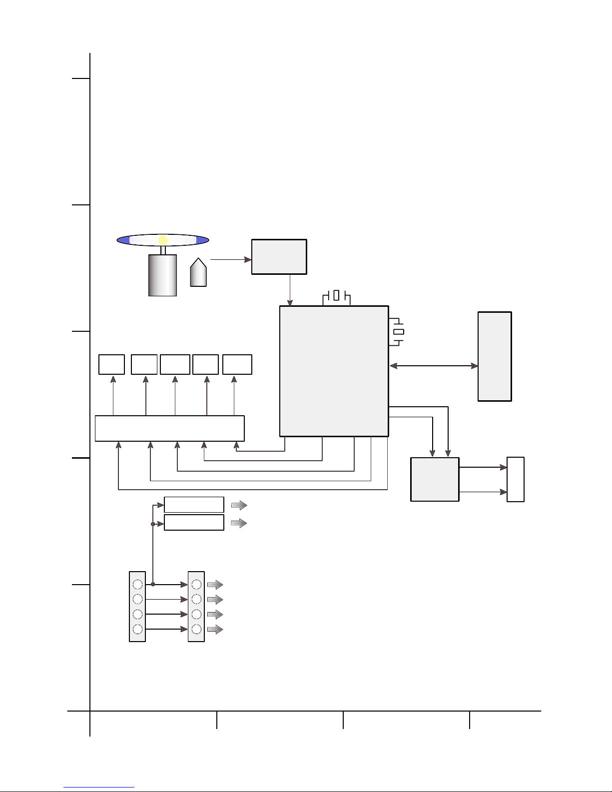
3.3V Reg
2.5V Reg
+3.3V
+5V
+12V
+2.5V
GND
GND
+5V
+12V
GND
GND
SPINDLE
MOTOR
SLED
MOTOR
LOADING
MOTOR
FOCUS
COIL
TRACKING
COIL
M63026FP
MOTOR DRIVE
Disc
Motor unit
Optical
Pick-up
CXA2581N
RF Amp.
CXD3045R
DSP + Decoder +
DRAM +
System controller
33.86MHz
40MHz
I/F Cable
H
O
S
T
AUDIO
Circuitry
R-ch
L-ch
Line-out
A B CD
1
2
3
4
5
32
BLOCK DIAGRAM

2. Trouble List (Circuit)
A. LED doesn’t light.
B. Pick-Up doesn’t move to the inner-track.
C. The Laser of Pick-Up doesn’t light.
D. Pick-Up lens doesn’t move up and down.
E. Disc doesn’t rotate.
F. TOC isn’t read. (The LED turns on, but doesn’t flicker.)
G. During Audio CD Play, LED flickers, but Speaker is silent.
21
TROUBLESHOOTING GUIDE
1. Initial Lead-in Operation
Reset or Power-On.
LED Flickers.
Pick-Up moves to the inner-Track.
Laser on the Pick-Up lights.
Focus Search (through moving up and down the lens of Pick-Up)
Focus Servo On (FOK :H, FEO(TP15) signal generation)
Rotate disc.
Tracking Servo On (TEO(TP14) Signal generation)
Spindle Servo On (SPO(TP25) Signal generation)
Read TOC Area (LED Flickers)
Search the Start of Data Area and then pause.
22
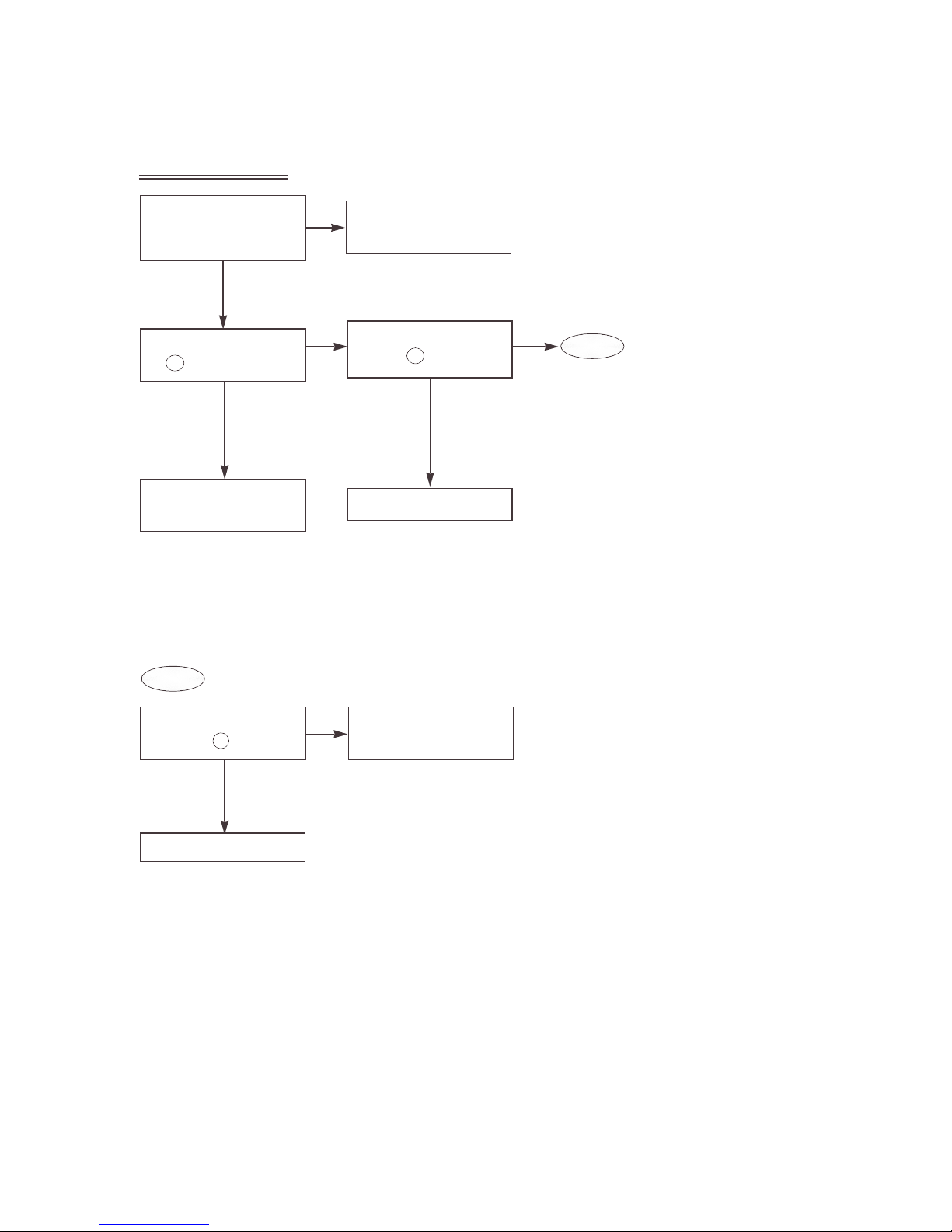
3. Troubleshooting Guide
A. LED doesn’t light.
Check Power Voltage
(TP1:3.3V, TP20:2.5V, TP2:12V)
Reference Voltage
[TP3:DVC(1.35V) and GND.]
Does “H” output in IC501
pin ?
Check and replace R705,
R706, Q701 and LED701.
Is the CLOCK Frequency of
IC501 pin 33.86MHz?
Check the power input
pattern.
Check IC501.
Check and replace
X501; 33.86MHz,
X502: 40MHz
Is the CLOCK Frequency
of IC501 pin 33.86MHz?
Check and replace IC501.
YES
OK
NG
YES
YES
NO NO
NO
109 171
171
A-1
A-1

23
B. Pick-Up doesn’t move to the inner track.
Do the signals appear at
IC501 pin , ?
(Refer to Fig. B-1.)
Do the signals appear in
PN301 pin?
Does “H” output at IC201
pin ?
Is the 1.35V at IC201 pin ?
Check the pattern from
IC501 pin to IC201
pin
.
Check IC501.
Check the R190 and
then replace IC102.
Check the PN301, and then
replace the Sled Motor.
YES
YES
YES
YES
NO
NO
Replace IC201.
NO
NO
73
41
25
74
106
41
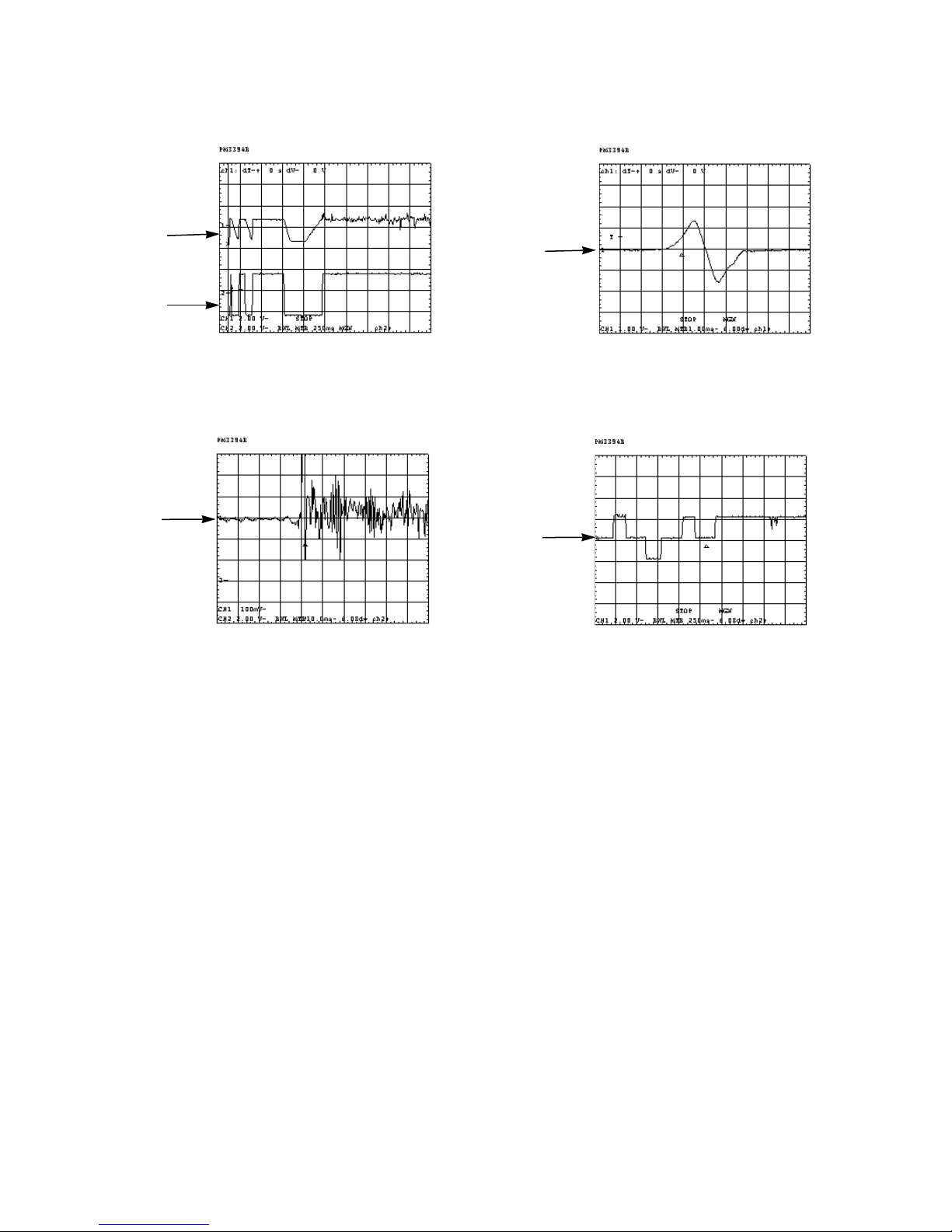
CH1
PIN74
DA0
CH2
PIN73
DA1
CH1 TP4
CH2 TP5
CH3 TP6
CH4 TP7
Fig. B-1. DA0 and DA1 Signals Fig. B-2. TP4, TP5, TP6 and TP7 Signals

Check the pattern from
IC501 pin to R225
and then replace IC501.
24
Does “Low” or “High”
output at IC102 pin ?
Is the voltage of IC102 pin
(LD) 2V?
Check Pick-Up FFC, PN101.
Check Q101, C101, C102
and then replace IC102.
Check R118 and replace
IC501.
YES
YES
NO
NO
1
4
12
Does the focus search signal
appear at FAO (TP9)?
(Refer to Fig. D-1.)
Is the 1.35V at IC201 pin ?
Check the R190 and then
replace IC102.
YES
YES
YES
NO
NO
Replace IC201.
NO
25
Does the focus search
signal appear between F+
(TP10) and F- (TP11)?
(Refer to Fig. D-2.)
C. The Laser of Pick-Up doesn’t light.
D. The Pick-UP lens doesn’t move up and down.
D-1

25
Check the pattern from
pin , of IC201 to
pin , of PN101.
Check the PN101, Pick-Up
FFC.
Replace the Pick-Up.
Replace PN101 or Pick-Up
FFC.
OK
OK
NG
34 35
14
CH1
TP9
(FAO)
CH1
TP10(F+)
TP11(F-)
Fig. D-1. FAO Signal Fig. D-2. Focus Search Signal
D-1

26
Does the signal appear at
the MDP (TP25)?
(Refer to Fig. E-4.)
Do the signals appear at
IC201 pin (W), (V),
and (U)?
Replace IC501.
Replace IC201.
YES
NO
NO
12
14
13
Check the pattern from
IC201 pin , , to
PN201 , , .
YES
OK
12 13 14
13 12 11
Check Spindle Motor FFC
and then replace the
Spindle Motor.
Does the signal appear at
FEO (TP15) when the
R504 opened?
(Refer to Fig. E-2.)
YES
YES YES
NO NO
Replace IC501.
Replace IC501.
Replace Pick-Up.
NO
Do the signal appear at
TP15 (FEO) and TP19
(SENS)?
(Refer to Fig. E-3.)
Does the signal appear at
FOK (TP18) during focus
search?
(Refer to Fig. E-1.)
E. Disc doesn’t rotate.
27
Fig. E-3. FEO Signal
CH1
TP15:
FEO
Fig. E-4. MDP Signal
CH1
TP25:
MDP
Fig. E-1. FOK, F+ Signal
CH1
TP10:
F+
CH2
TP18:
FOK
Fig. E-2. S-Curve (R505:Open)
CH1
TP15:
S-Curve
Tabla de contenidos
Manuales populares de Unidad de CD/CDR de otras marcas


SmartDisk
SmartDisk Firewire CD-R/W Manual de usuario

Axis
Axis CD-ROM SERVER Manual de usuario

LG
LG CRD-8322B Manual de usuario

Memorex
Memorex 32023234 - 52x32x52x External USB2.0 CD... Instrucciones de instalación

Yamaha
Yamaha CD Recordable/Rewritable Drive CRW3200 Manual de usuario

Sony
Sony CRX230AE Manual de usuario


