Define Instruments TEX-BAR Manual de usuario

TEX-BAR-MAN-15V05 (0903)Copyright © 2015 Dene Instruments
1
The TEX-BAR process controller oers
a 5-digit numeric display as well as a
0-100% front panel bar graph, for in-
stant, visualisation of your selected pro-
cess variable.
This versatile unit accepts both current
(0/4–20mA) and voltage (0–2/10V)
inputs, allowing easy interface with
a wide range of PLC and monitoring
systems.
TEX-BAR
4-20mA/0-10V Bar Graph
Order Codes
TEX–BAR Process controller + Bar graph
–HV
–LV
85–265V AC / 95–370V DC
15–48V AC / 10–72V DC
Options
-R2
-R4
2 x relay outputs
4 x relay outputs
-A 1 x mA/V analog output
-S2R 1 x RS232 (RJ11 terminal)
-S4S 1 x RS485 (screw terminal)
Contents
1 - Specications .............................. 2
2 - Front Panel & Display ................. 3
3 - Wiring .......................................... 5
4 - Dimensions & Installation .......... 8
5 - Input Header Adjustment ........ 10
6 - Input Setup & Calibration ........ 12
7 - Setpoint Setup ........................... 19
8 - Setpoint Open Access................ 22
9 - Reset PIN Numbers /
View Firmware Vsn ................... 22
A - Appendix A - Serial Modes........ 23

TEX-BAR-MAN-15V05 (0903) Copyright © 2015 Dene Instruments
2
1 SPECIFICATIONS
Input
Process input signal 4–20mA, 0–20mA,
0–2V, or 0–10V
Power supply
HV= 85–265V AC / 95–370V DC, or
LV= 15–48V AC / 10–72V DC
Excitation 24V DC (50mA max)
Sampling rate 10Hz
Resolution 16 bit
Accuracy 0.05% of reading
Ambient dri 50ppm/°C typical
Mains frequency Select 50/60Hz
Relay Output
Number of relay outputs None, 2, or 4
Relay output type 5A form A (3A 240V
AC max or 3A 30V DC max)
Analog Output
Number of analog outputs None or 1
Analog output type Isolated 16 bit
4–20mA/0–10V
Comm Port
Number of comm ports None or 1
Comm port options
S2R= Isolated RS232, RJ terminal, or
S4S= Isolated RS485, screw terminal
Programming
Buttons Up, Down & Prog (P) buttons
Factory calibrated for all input ranges.
Set up for 4–20mA by default. (Header
adjustment required for voltage input.)
Security Input and setpoint setups are
independently PIN protected
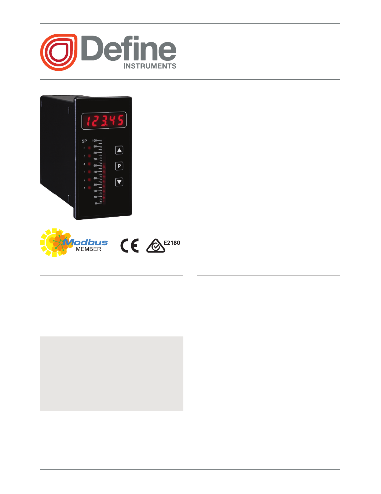
Display
Display type LED display with 0-100%
bar graph (51 segments), 3 buttons
LED indicators 6 setpoint indicator LED's
Digits 1 row of 5 digits, 8mm (0.3"),
7 segment alphanumeric LED
Construction
Casing Panel mount case
Ingress protection rating IP65 dust/
splash proof (face only)
Dimensions (H x W x D)
96 x 48 x 120mm (3.78 x 1.89 x 4.72")
Panel cutout 92 x 45mm (3.62 x 1.77")
OPTIONAL
OPTIONAL
OPTIONAL

TEX-BAR-MAN-15V05 (0903)Copyright © 2015 Dene Instruments
3
2 FRONT PANEL & DISPLAY
2.1 - Front panel
The SP LED's are used to indicate
active setpoints.
The 'Up' button is used to access
the Input Setup & Calibration menu
(Section 6).
It is also used to scroll through options
or increase values in the setup menu.
The 'Prog' button is used to save
your settings and advance to the next
step in the setup process.
The 'Down' button is used to access
the Setpoint Setup menu (Section 7)
and the Setpoint Open Access menu
(Section 8).
It is also used to scroll through options
or decrease values in the setup menu. 48mm (1.89")
96mm
(3.78")
2.2 - Display brightness
To adjust the display brightness, press the and buttons together from the
main display. BRI appears and toggles with the current brightness setting.
Use the and buttons to adjust the LED backlight, and then press to nish.

TEX-BAR-MAN-15V05 (0903) Copyright © 2015 Dene Instruments
4
2.3 - 7 Segment display characters
The 5 digit, 7 segment display is chiey intended for displaying numbers. However
when navigating the setup menus, alphabetic characters will also be displayed. This
table is provided for your reference during setup, if required:
ABCDE FG
HI JKLM
NOPQR S T
UVW XYZ
!?/

TEX-BAR-MAN-15V05 (0903)Copyright © 2015 Dene Instruments
5
3 WIRING
BEFORE YOU BEGIN WIRING, ensure that the unit is switched o and the power
supply is disconnected.
3.1 - Pinouts
Key
3.1A Analog Input (See 3.2)
3.1B Function Pins (See 3.6)
3.1C Power Supply HV/LV (See 3.7)
3.1D Relay Output (See 3.3)
3.1E Serial Port (See 3.5)
3.1F Analog Output (See 3.4)
A
D
B
C
E
F
3.2 - Wire the analog input See 3.1A
Wire the analog input as required for your application, referring to the diagrams
below. (For instructions on changing the input type header, see Section 5).
EXTERNAL
+ Supply
-
Supply
+ POS
+ 24V EXC
-
NEG
N
/
C
I/V
+ Signal
-
Signal
2-wire Current/Voltage Input
External excitation used

TEX-BAR-MAN-15V05 (0903) Copyright © 2015 Dene Instruments
6
+ POS
+ 24V EXC
-
NEG
SENSOR
N
/
C
I
2-wire Current Input
Loop powered sensor
+ Signal
-
Signal
/
-
Supply
+ POS
+ 24V EXC
-
NEG
I/V + Supply
2-wire Current/Voltage Input
Controller supplied excitation
3.3 - Wire the relay outputs (if installed) See 3.1D
If your controller has relay outputs installed, wire them as shown below. Relays can
be programmed to operate within the total span range of the controller.
SP2
SP1
–R2
SP2
SP1
SP
4
SP3
–R4
3.4 - Wire the analog output (if installed)
See 3.1F
If your controller has analog output installed, wire it as
shown for either voltage (0–10V) or current (4–20mA).
–V
+V
–mA
+mA
–A

TEX-BAR-MAN-15V05 (0903)Copyright © 2015 Dene Instruments
7
3.5 - Wire the serial port (if installed)
See 3.1E
If your controller has serial port tted, wire it as
shown in the applicable diagram.
›S2R RS232, RJ11 terminal
›S4S RS485, screw terminal
N/C
SGND
+5V DC (option)
RXD
TXD
N/C
–S2R (RS232)
D
-
D +
SGND
–S4S (RS485)
3.6 - Wire the function pins
See 3.1B
Connect external switches to enable a function
to be executed when its switch is activated.
›Hold Holds the current display value
›Test Resets the meter
Test
Hold
COM
NC
NC
3.7 - Wire the power supply See 3.1C
Wire your controller for either low or high voltage power supply, as shown in the
diagrams below. Check the label on the unit against the colour of the connector:
›Orange = High voltage
(85–265V AC, 95–370V DC)
›Black = Low voltage
(15–48V AC, 10–72V DC)
Once you have completed the
wiring process it is safe to switch
on your power supply.
High voltage
(–HV)
+DC/live AC
–DC/neutral AC
HV power
supply
Low voltage
(–LV)
+DC/live AC
–DC/neutral AC
LV power
supply
NEVER CONNECT YOUR LOW VOLTAGE UNIT TO MAINS POWER.

TEX-BAR-MAN-15V05 (0903) Copyright © 2015 Dene Instruments
8
4 DIMENSIONS & INSTALLATION
4.1 - Case dimensions
Cabling
Allowance
48mm
(1.89")
45mm
(1.77")
120mm (4.72") 39mm (1.54")
155mm (6.10") minimum de
p
th re
q
uired behind
p
anel
4mm (0.16")
Cabling
Allowance
96mm
(3.78")
92mm
(3.62")
120mm (4.72") 39mm (1.54")
155mm (6.10") minimum depth required behind panel
4mm (0.16")

TEX-BAR-MAN-15V05 (0903)Copyright © 2015 Dene Instruments
9
4.2 - Installation instructions
Before installing the unit in the panel, it is recommended that you FIRST read
Section 5 to conrm that the input header does not need to be adjusted.
A Prepare the Panel Cutout to
45 x 92mm ±.5 (1.77 x 3.62" ±.02),
as shown below.
Allow at least 155mm (6.10")
depth behind the panel to accom-
modate the meter body and pro-
truding cabling.
B Remove the Mounting Clips from
the meter back.
C Slide the Panel Gasket over the
rear of the unit to the back of the
Meter Faceplate.
D From the front of the panel, insert
the meter into the Panel Cutout.
Holding the unit in place, engage
the Mounting Clips so that the tabs
snap into place over the notches on
the case.
E To achieve a proper seal, tighten
the Screws evenly until the unit sits
rmly against the panel. Do not
over-tighten the screws.
Panel
Meter Faceplate
Panel Gasket
Mounting
Clips
Screws
92mm ±.5
(3.62″ ±.02)
45mm ±.5
(1.77″ ±.02)
Panel Cutout

TEX-BAR-MAN-15V05 (0903) Copyright © 2015 Dene Instruments
10
5 INPUT HEADER ADJUSTMENT
The analog input board for the TEX-BAR has a header which can be set to 3 positions,
depending on your input type and range, as per the table below:
Header Position Used For
20mA 0–20mA and 4–20mA input ranges (default setting)
2V 0–2V input range
10V 0–10V input range
5.1 - Do I need to shi the input header?
In most cases the input header does not need to be changed from its default posi-
tion of '20mA' (suitable for 0–20mA and 4–20mA inputs).
You will need to shift the input header if:
›You are using the 0–2V or 0–10V input range, or
›You are changing your input type or range from a previous setup
5.2 - How to shi the input header
A If the meter is already installed, remove it from the panel, and unplug all plugs
from the back of the unit.
B Using a small screwdriver or similar implement,
press downward into one of the slots at the
rear of the case.
This will disengage the tab which holds the
back plate on, allowing it to be gently
levered away at one corner.
C Holding the loosened corner open
with one hand, disengage the le-
ver on the opposite slot.
Tabla de contenidos
Otros manuales de Controladores de Define Instruments


