DAYLIFF HPW150 Instrucciones de instalación
HPW
All in One Heat Pump
HPW150 HPW200 & 300

1
2
4. INSTALLATION 12
5. OPERATION AND MAINTENANCE 25
6. TROUBLE SHOOTING 26
7. TERMS OF WARRANTY 27
© Davis & Shirtliff Ltd 2023
Contents herein are not warranted
3. EQUIPMENT CONTENTS 4
2. SYMBOLS & WARNINGS
1. SPECIFICATIONS
Dayliff HPW Heat Pump Hot Water Systems are designed for all domestic water heating
applications that utilise the high efficiency benefits of heat pump technology. The integral
systems combine a hot water storage tank with an efficient heat pump that generates
heat from ambient air by utilising the natural heat generating phenomenon of the gas
evaporation/condensation cycle. This is transferred to the stored water by circulation
through a coil type heat exchanger in the tank. Tank construction is carbon steel with
internal enamel coating and a magnesium anode is fitted for cathodic protection against
corrosion. The tank is lined with high grade thermal insulation for heat retention.
Particular features are:-
0 0
• HPW heat pumps work best under ambient temperature of between -7 C to 43 C
• High quality integral heat pump fitted on top of the hot water cylinder with quiet
GMCC compressor that provides a Coefficient of Performance (COP) of up to
0 0
4.16 (at 20 C Ambient temp, 15 C Water temp) and settable hot water
0
temperature of up to 75 C. This provides up to 80% power savings compared to
conventional element heaters.
• Tube type heat exchanger coiled externally around the water tank for performance
and safety with inbuilt sterilising function
• Integral 2kW electric heating element for temperature boosting
• Digital controller for operational and timer settings and fault indication
• Supplied complete with ozone friendly R134A regrigerant gas for optimal
performance
Dayliff HPW systems are high efficiency, high performance water heaters and are the ideal
solution for all residential hot water supply requirements.
Congratulations on selecting a Dayliff Heat Pump Hot Water Systems.
They are manufactured to the highest standards and if installed and
operated correctly will give many years of efcient and trouble free
service. Careful reading of this Installation Manual is therefore
important, though should there be any queries they should be referred
to the equipment supplier.
1. SPECIFICATIONS
HPW150 HPW200 & 300

2. SYMBOLS & WARNINGS
The unit should be reliably earthed before usage, otherwise
might cause death or injury.
WARNING
Do not remove any labels or parameter plate on instructions
attached .
WARNING
Installation, repair and maintenance should be carried out by
a qualied professional in accordance with local regulation.
WARNING
This is a household appliance and necessary protection
against electric fault should be provided.
TECHNICAL SPECIFICATIONS
Hot Air
Inlet
Cold Water
Outlet
Controller Heat Pump Unit
Water Tank
Drain Outlet
Hot Water Outlet
Electric Heater
Cold Water Inlet
Water Tank Volume, Liters
Heating Capacity, kW
Rated/Max Input Power, kW
Fan Flow
Rated/Max Current, A
Net Dimensions, mm
Net Weight, kgs
Model
500x500x1670
92 105 130
HPW150
150
HPW300
300200
2.5
0.6/3
Side Top
2.7/15
HPW200
620Diax1638 620Diax2038
Inlet/Outlet ¾”
Any modication and improper repair is not advised as it may
cause re, electric shock and injury.
WARNING
Ensure electrical supply is compatible with the Rated Current
value should not be less than 10A and power.
WARNING
Install the equipment in a cool dry place and that is well
ventilated and away from children. The power plug should be
installed about 1.8m above ground for safety
WARNING
Do not install this equipment indoors. As it may cause overow,
noise or indoor temperature to drop drastically.
WARNING
The place must have enough space for installation and
maintenance.
WARNING
Ensure that inlet or outlet airow is not obstructed. Keep away
from wind and combustible gases.
WARNING
Install on a at surface that can bear heat pumps weight and
easy to install vertically. In addition, the surface should not
increase noise or vibrations.
WARNING
High temperature, saline conditions and long term exposure
to harsh elements may decrease lifetime of products. Ensure
proper maintenance for long life. Also avoid installing in sites
with mineral oil, corrosive gases, strong vibrations and strong
electromagnetic waves to extend equipment life.
WARNING
Do not install in kitchens where there is cooking gas and oil
spills and splatters
WARNING
3

Do not touch fan with your hands or other objects else may
result in injury.
WARNING
ŸThe condenser coil is wrapped around the stainless tank, and does, not come in to
contact with water directly, providing more safety and health.
ŸThe maximum outlet water temperature is 60ºC.
ŸFlexible installation is achieved by varying air inlet and outlet duct piping as below;
Equipment is provided with complete isolation between water
and electricity, without electric shock problem, more safety.
NOTE
Refrigerant Outlet
Refrigerant Inlet
Fig 1: Single Coil Layout
3.1 Equipment Contents
Fig 2: Inlet/Outlet Variations
3. INSTALLATION
4
5
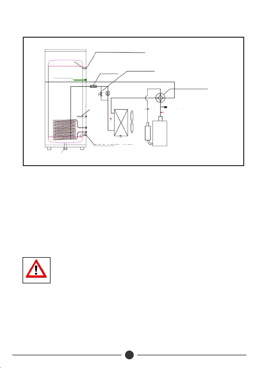
ŸThe unit is provided with automatic start-up and shutdown, automatic defrosting by
by way of revising refrigerant cycle to save the extra operation.
Ÿ A non return valve must be installed on the cold water inlet.
ŸEEV: Electronic expansion valve, the opening is regulated according to the discharge
air temperature of compressor.
ŸHigh Pressure Switch: When the discharge pressure of compressor is 27 bar or
higher, the protection switch will be triggered, and if the discharge pressure is down to
20 bar, the protection switch will be recovered
ŸFan: Centrifugal fan with three speeds to draw in air.
ŸCompressor: Concentrates and increases heat to form a very hot gas which is
passed to the heat exchanger to heat pool water.
ŸEvaporator: Copper tube with aluminium type heat exchanger that turns
refrigerant into gas..
ŸEH: Electrical heater for temperature boosting.
This heat pump is heavy and needs atleast two people to move
0
and install it. Also ensure to carry it at an angle no less than 75 .
WARNING
Fig 3: Heat Pump Component Layout
3.2 Siting
ŸEnsure to leave enough space for easy installation and maintenance
Hot water outlet
One-way valve
4-way valve
High pressure switch
Compressor
Cold water inlet
Dryer
Magnesiarods
Evaporator
EEV
EH
Fan

6
Air Outlet
Barrier
Air Inlet
>200mm
>800mm
>200mm
Control Panel
>500mm
>200mm
>200mm
Fig 4: Installation Layout
ŸIf heat pump is installed in the basement or indoor or other airtight spaces, ensure
there is sufficient air circulation. The air duct total length should be equal or less than
6 meters, and the duct diameter should be equal or more than 150 mm.
Condensed
water outlet
Water for
domestic use
mixing valve
Temperature Sensor
Cold Water Inlet
Magnesium Rod
Magnesium Rod
Hot water outlet
Y-Type Filter
Tap Water
Ball Valve
Relief Valve
Drainage
Outlet
Floor Drain
Fig 5: Pipe Line Connection Diagram
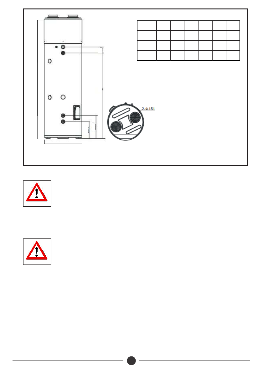
7
A
E
B
CD
F
Model
HPW150
HPW200
HPW300
A B C D E F
1670 1214 246 346 198 500
1638 1013 280 380 100 620
2038 1413 280 380 100 620
3.3 Water Pipe Installation Instructions
The relief valve needs to be descaled to remove calcium
carbonate and ensure no obstacles. Outlet temperature of
drainage port may be high and caution must be exercised.
NOTE
ŸKeep the handle of safety valve free and ensure drainage port is kept free of debris.
ŸAfter setting up pipeline, open the valve both the cold and hot water valve to fill the
water tank and close inlet valve when water overflows from water outlet. Inspect the
pipeline and ensure that there is no water leakage.
ŸWhen intake pressure is below 1.5 Bar, a booster pump may be installed. When
intake pressure is greater than 6.5 Bar a relief valve must be installed to protect the
water tank from early failures.
ŸDuring operation, condensed water droplets may be formed, ensure proper drainage
is provided as guided below
Do not use iron pipe to connect to heat pump, instead use CPVC
pipe, PPR pipe or UPVC pipe
WARNING
ŸWater pipes work life should not be less than heat pump’s work life.
ŸInstall relief valve of G1/2’’, 8bar and ensure that the drainage pipe which connects
with the relief valve, is not blocked.
Fig 6: Connection Dimensions
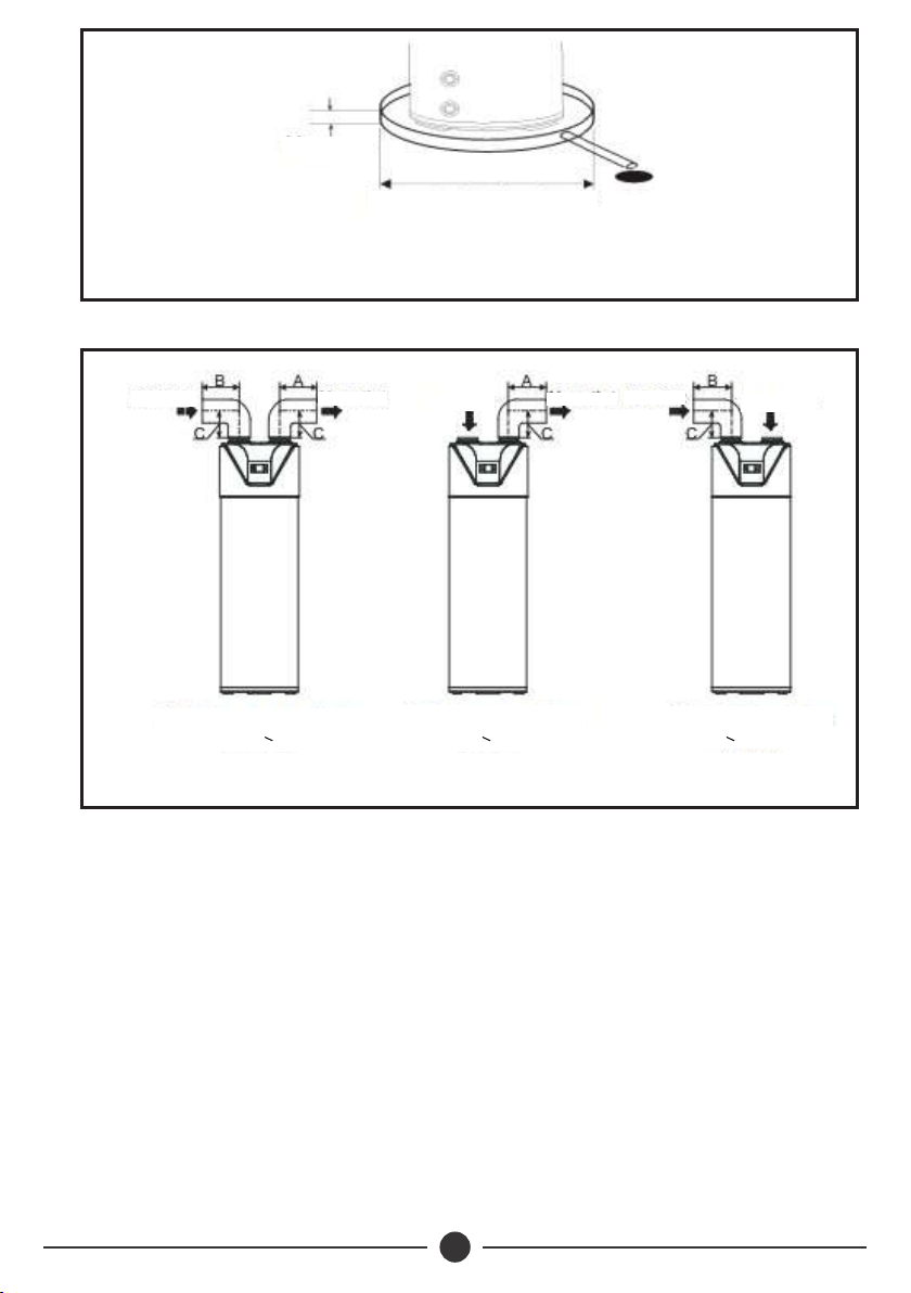
8
Diameter atleast 50mm larger
than heat pump
Max 2.2"
Fig 7: Drainage Layout
3.4 Sitting and Air Duct Installation Instructions
Fig 8: Inlet/ Outlet Duct Designs for HPW200/300
(1) Air inlet and outlet with duct
A+B < 6m
(2) Only air outlet with duct
A< 6m
(3) Only air inlet with duct
B< 6m
Air inlet Air Outlet Air inlet Air Outlet Air inlet Air Outlet
ŸAs a rule, heat pumps should be installed outdoors. However by varying the design of
air intake and outlet ducts, the heat pump can be used to condition cold air in the
room.
ŸIt is recommended to install the unit by only air outlet with duct (Scheme 2 ) in
summer that could charge fresh cold air into room. ( The heat pump is installed
outdoor ).
ŸScheme 3 is preferable in winter where there is other heat source in the room. ( The
heat pump is installed outdoor ).
Este manual sirve para los siguientes modelos
2
Otros manuales de Bomba de calor de DAYLIFF

Manuales populares de Bomba de calor de otras marcas


Mitsubishi Electric
Mitsubishi Electric PUZ-SWM60VAA Manual de usuario

Dimplex
Dimplex LI 16I-TUR Guía del usuario

Carrier
Carrier WSHP Open v3 Guía de configuración rápida

TGM
TGM CTV14CN018A Manual de usuario

Carrier
Carrier 38MGQ Series Manual de usuario

Kokido
Kokido K2O K880BX/EU Guía de solución de problemas

Viessmann
Viessmann VITOCAL 300-G PRO Type BW 2150 Guía rápida

Carrier
Carrier 48EZN Manual de usuario

Viessmann
Viessmann KWT Vitocal 350-G Pro Series Instrucciones de funcionamiento

Ariston
Ariston NIMBUS Manual de usuario

Weishaupt
Weishaupt WWP L 7 Guía del usuario

GE
GE Zoneline AZ85H09EAC Manual de usuario