daviteq iConnector STHC Manual de usuario

This chapter is to provide the general guides for all kind of iConnector with SKU: STHC. It includes the following guides:
* Principle of operation of iConnector STHC; * How to Wiring the iConnector * How to Config iConnector via offline cable;
* How to Configure Modbus commands for iConnector; * How to Configure Alarms & Event; * How to Trouble-shoot
iConnector; ...
General Information
I. Specification of iConnector STHC
II. Principle of operation of iConnector STHC
III. Offline configuration for iConnector
IV. Insert SIM Card for Cellular iConnector
V. Installation iConnector STHC
VI. How to add iConnector STHC to Globiots Server System?
VII. Modbus Configuration for iConnector STHC on Globiots
VIII. Parameter Configuration for iConnector STHC on Globiots
IX. Alarm & Event Configuration for iConnector STHC on Glbiots
X. Configuring special functions of iConnector on Globiots
XI. Troubleshooting iConnector and Globiots
GENERAL GUIDE FOR
ICONNECTOR STHC

STHC-MN01-EN-01
JUL-2020
SKU
STHC
HW Ver.
3.3
FW Ver.
3.5
HW Ver.
FW Ver.
Release Date
Functions Change
3.3
3.5
Aug-2020
Manufacturer
Daviteq Technologies Inc
No.11 Street 2G, Nam Hung Vuong Res., An Lac Ward,
Binh Tan Dist., Ho Chi Minh City, Vietnam.
Tel: +84-28-6268.2523/4 (ext.122)
Email: info@daviteq.com | www.daviteq.com
Distributor in Australia and New Zealand
Templogger Pty Ltd
Tel: 1800 LOGGER
Email: contact@templogger.net
General Information
This document is applied for the following products
A. Functions Change Log
B. Support contacts

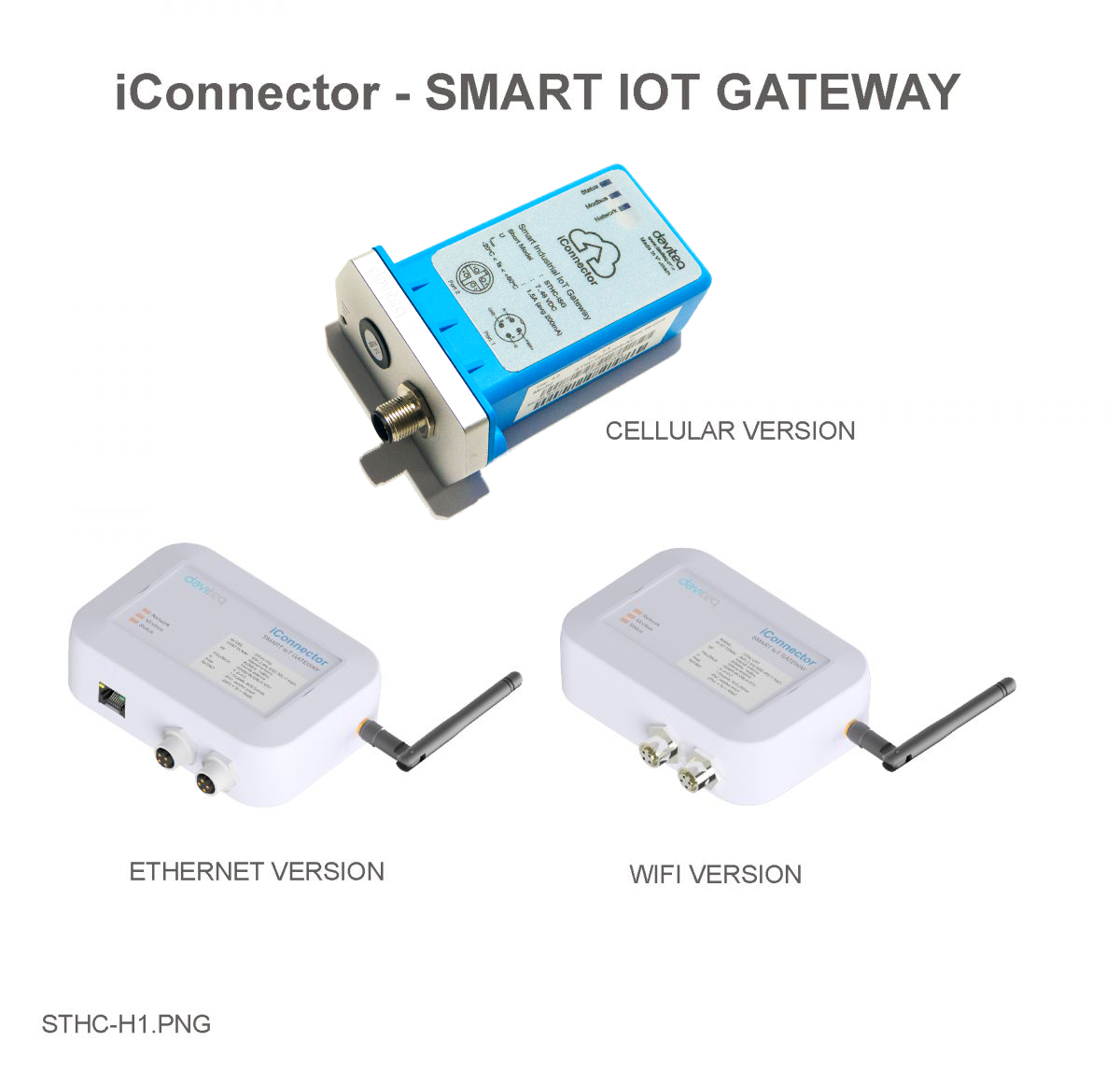
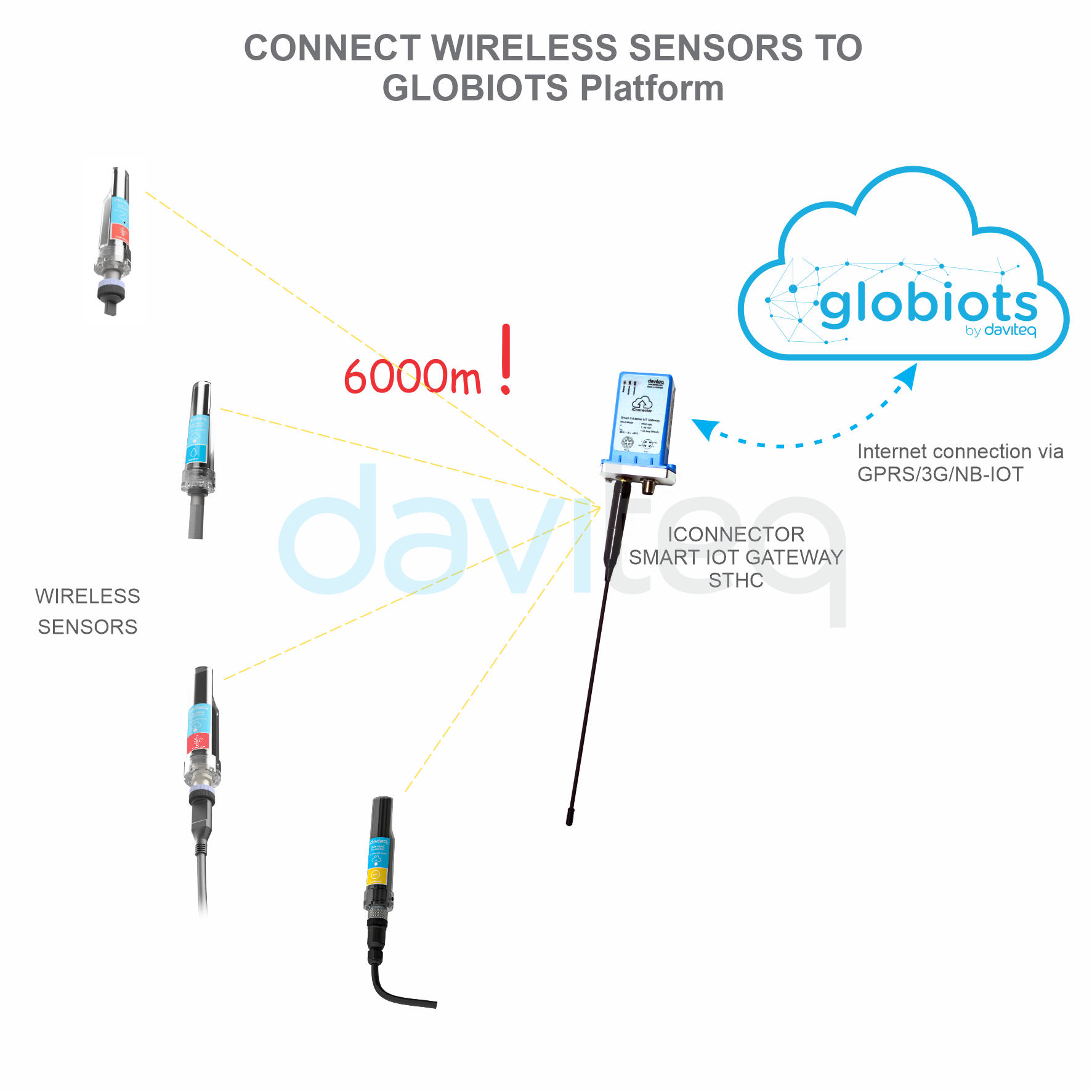
STHC is a Smart IoT Gateway, aka iConnector, a main component in any IoT application. iConnector has a role to
connect the real World's things like sensors, meters, ,machines...to server system for data logging, data analytics,
monitoring & controls...iConnector support multiple Industrial Fieldbus like Modbus, EthernetIP, Profinet, CClink,
Wireless sensor network...It connects to server system via LAN/WAN as Ethernet, WiFi or Cellular.
Host Communication Cellular type
GPRS Quadband (850/900/1800/1900)/3G-Dual band (2100/900)/3G- Penta
Band (2100/1900/850/850Japan/900/800Japan),standard internal antenna,
optional external antenna
Host Communication Etherner type
01 x RJ45 port, 10Mbps
Host Communication WiFi type
802.11b/g/n, 2.4Ghz,internal antenna
GPS
option, only available on GPRS version or 3G-Penta band version
Host communication supports
TCP/IP, UDP/IP, FTP, HTTPS, SNMP...
Fieldbus communcation
ModbusRTU x 01 port, 31 slaves, max 19.2 kpbs
Vietnam Type Approval
Cerification
QCVN 54:2011/BTTTT, QCVN 15:2015/BTTTT (DAVITEQ B00122019)
Optional
Integrated wireless co-ordinator with external antenna or internal antenna
Optional
Internal buzzer (to replace Relay 1)
Power supply
7..48VDC, avg 200mA, peak 1.5A
I. Specification of iConnector STHC
1.1 Introduction
1.2 Specification

Back-up battery
Lithium Super Capacitor
On-board memory & sensors
2MB Flash, PCB temperature sensor
Electrical connectors
M12, 4-pin, coding A or 9mm Power Plug and USB port
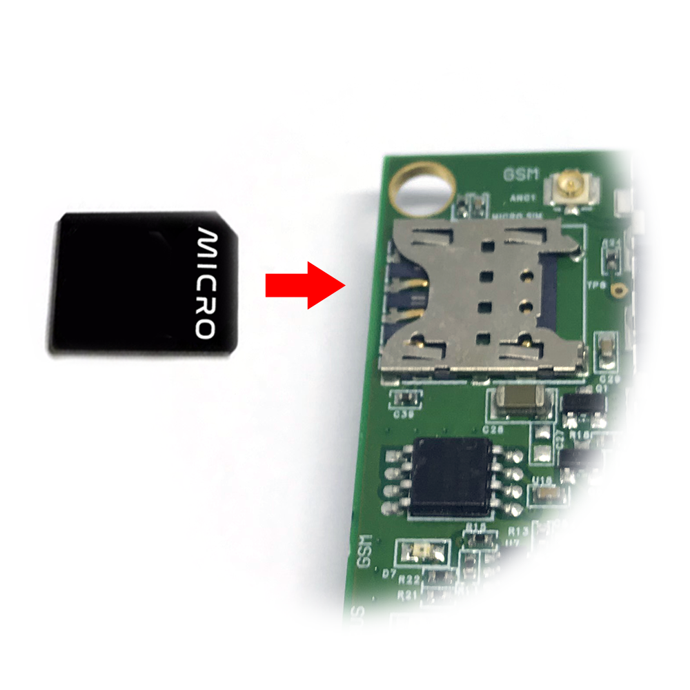
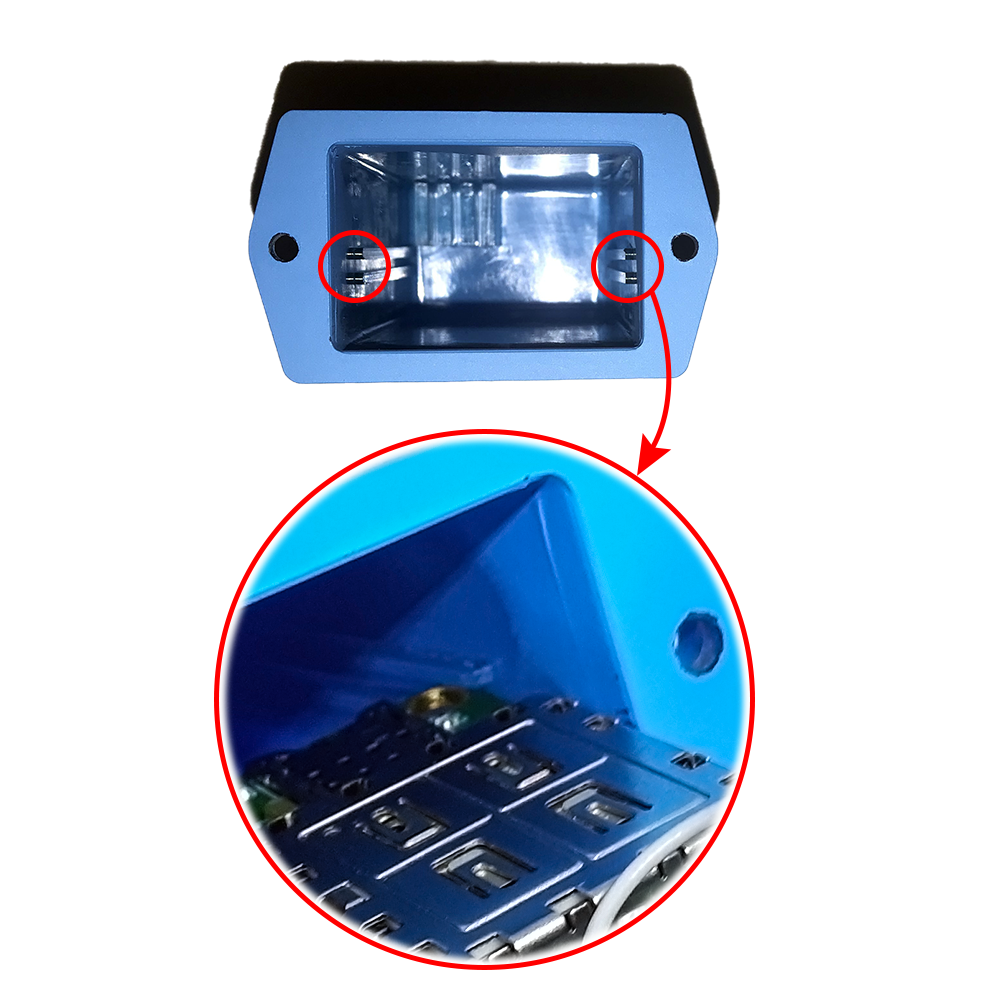
SIM slot
01 x micro-SIM (cellular versions only)
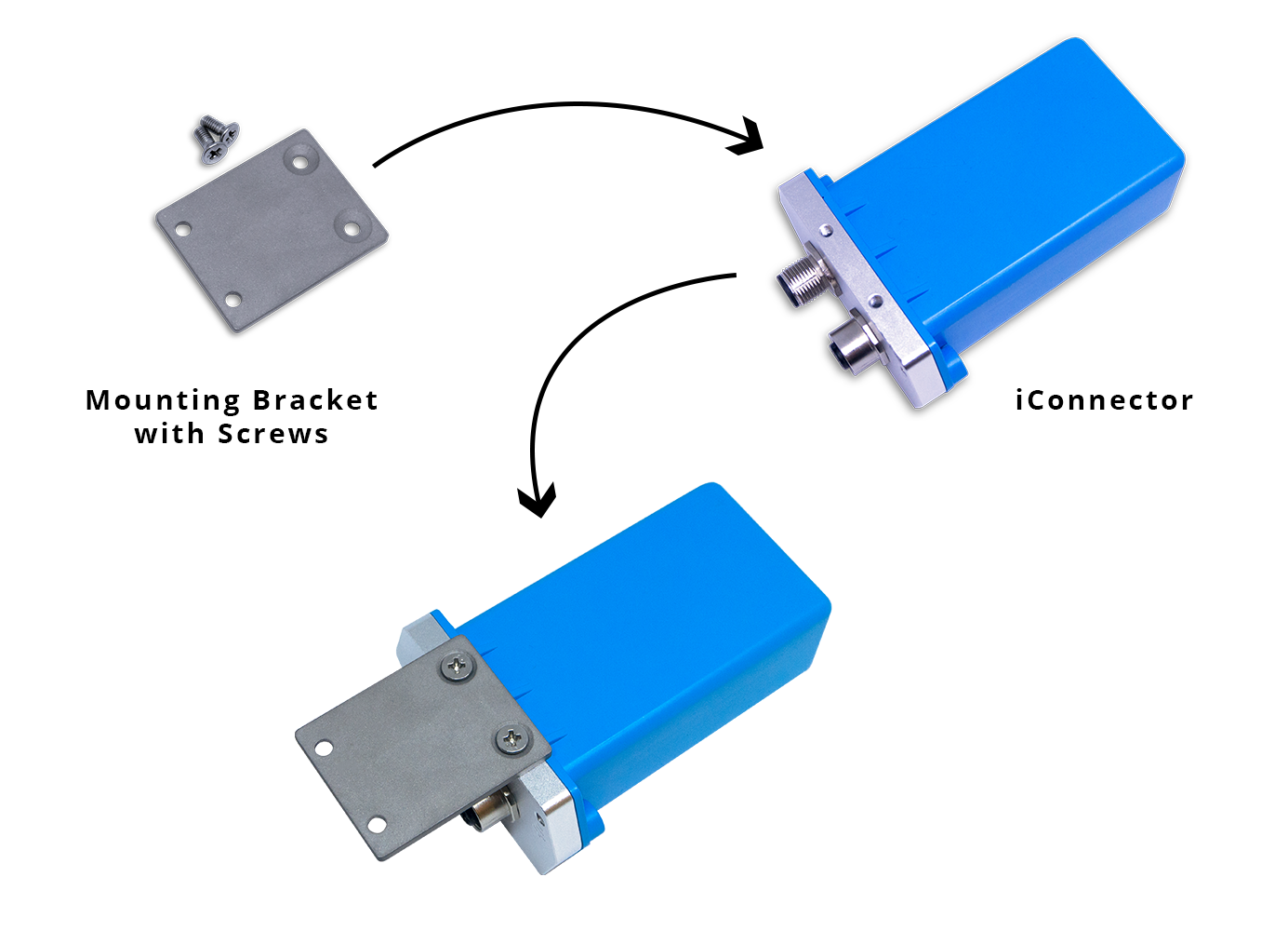
Included accessories
mounting bracket for wall mount (cellular version only)
Operating Temperature/Humidity
-20 .. + 60 degC / 95%RH, non-condensing
Housing/Protection
Aluminum+Polycarbonate for Cellular version, anti-UV plastic for Ethernet/WiFi
version. All version is IP67 protection
Dimension
H106xW73xD42 for Cellular version, H130xW90xD40 for Ethernet/WiFi
versions
Net weight
190 grams for Cellular version, 350 grams Ethernet/WiFi versions
Relay outputs
02 x relay SPST NO contact, 125VA[email protected] or 24VDC@1A

Status
Meaning
Fixed ON
iConnector has been supplied with external power
Blinking (4 seconds blink 1
time)
Without external power, iConnector is using battery.
Blinking (2 seconds blink 1
time)
Low battery warning (Used for type D battery version)
Status
Meaning
Fixed ON
Modbus connected
Blinking (1 seconds blink 2
time)
Connection errors (wrong configuration of baudrate, noise, …)
OFF
No modbus connection
Status
Meaning
Fixed ON
Connecting with Globiots
Blinking (1s change state)
Initializing wifi generator, waiting for configuration via phone or modbus tool (For
iConnector wifi)
OFF
No connection with Globiots
Address
Size
(bytes)
Memory type
Read/Write
Description
0-0x1FFF
8096
FLASH
R/W
Save active configuration, do not allow log,
realtime.
0x2000-
0x22FF
768
RAM
R
Save data read from modbus slaves.
II. Principle of operation of
iConnector STHC
2.1 General operation principles of
iConnector
2.1.1 LED meaning
2.1.1.1 LED status
2.1.1.2 LED modbus
2.1.1.3 LED network
2.1.2 Memory Map

0x2300-
0x24FF
512
RAM
R
The intrinsic data of iConnector
0x3000-
0x30FF
256
RAM
R/W
0x5000-
0x50FF
256
FLASH
R/W
0x6000-
0x6FFF
4096
RAM
R
Save data read from modbus slaves
Data address area: 0x2000-0x22FF (768 bytes), and 0x6000-0x6FFF (4096 bytes).
Controller address area: 0x3000-0x30FF (256 bytes, without flash storage), and 0x5000-0x50FF (256 bytes,
with flash storage).
256 bytes;
Save in flash (when power is lost, will keep the same value);
Allows reading, and writing from Globiots;
Allow log (realtime);
Allows Modbus write to Slaves;
It is not allowed to store data read from Modbus Slaves.
Up to 20 different log cycles;
320 log parameters maximum for all log cycles.
Up to 120 log parameters per log cycle.
Support modbus RTU.
Address slave 1… 247.
It is not allowed to set address slave = 0.
Baudrate 4800/9600/19200.
Parity none / odd / even.
Up to 100 modbus instructions.
The address area for storing read data: 0x2000-0x22FF (768 bytes), and 0x6000-0x6FFF (4096 bytes).
Controller address area: 0x3000-0x30FF (256 bytes, without flash storage), and 0x5000-0x50FF (256 bytes, with
flash storage).
Read up to 200 parameters.
If all parameters are float (4 bytes) then read up to 140 parameters.
The fastest realtime sending frequency is 1 second.
Up to 28 alarms.
Supported data types:
Address area 0x5000-0x50FF
NOTE:
Flash recorded about 100,000 times will be damaged so do not use this area to contain the value is changed
several times.
2.1.3 Logged data
2.1.4 Modbus
2.1.5 Realtime
2.1.6 Alarm

PrmType
Description
# Byte
Range
1
BYTE
1
0 to 255
2
UINT16
2
0 to 65,535
3
UINT32
4
0 to 4,294,967,295
4
FLOAT
4
-/+3.40282347 * (10^+38)
5
INT16
2
-32,768 to 32,767
6
INT32
4
-2,147,483,648 to 2,147,483,647
The event table is 1024 bytes.
The number of events depends on the short length of the event configured.
Supported data types:
PrmType
Description
# Byte
Range
1
BYTE
1
0 to 255
2
UINT16
2
0 to 65,535
3
UINT32
4
0 to 4,294,967,295
4
FLOAT
4
-/+3.40282347 * (10^+38)
5
INT16
2
-32,768 to 32,767
6
INT32
4
-2,147,483,648 to 2,147,483,647
Every 15 seconds send health pack 1 time.
There are 2 relays:
Relay control address 1: 0x3100.
Relay control address 2: 0x3101.
Value
RSSI dBm
Condition
2.1.7 Event
2.1.8 Health data
2.1.9 Relay
2.2 iConnector Cellular
2.2.1 GSM signal quality

0-9
≤-113 to -95
Marginal
10-14
-93 to -85
OK
15-19
-83 to -75
Good
20-31
-73 to ≥-51
Excellent
99
not known or undetectable
Value
Status
0
Connect to the server: OK
1
Connect to network operator: OK, the server is not connected yet
2
Communicate with GSM modem with AT command: OK
3
The GSM modem is starting
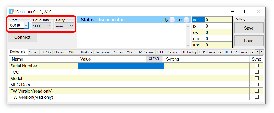
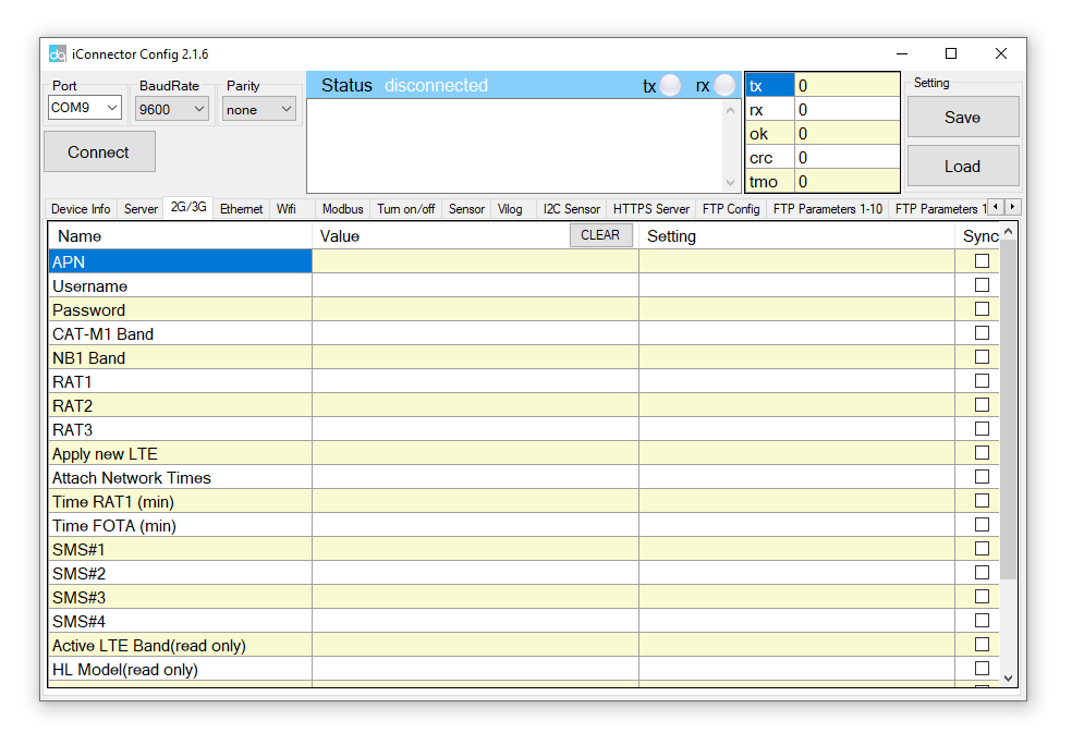
Use the iConnector Config Software to connect and configure iConnector
Open the 2G / 3G tab, then fill in the APN information of the SIM Card (APN, Username, Password,..) in Setting.
Finally click Sync to configure
2.2.2 GSM status
2.2.3 APN Configuration
Refer to section 5 for more details about how to use Configuration Cable.
Refer to section 6 for more details about how to insert SIM Card.
Refer here for more details on how to add sensor to the iConnector integrated Co-ordinator.


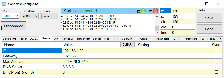
IP
Static IP configuration for iConnector. Example: 192.168.1.30
Gateway
Configure gateway
DNS Server
Configure DNS Server
DHCP
0 (Off) / 1 (On)
If DHCP = 0, it's mean Not using DHCP → Static IP
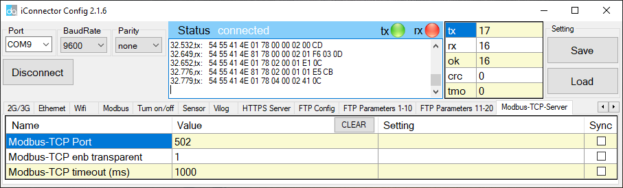
Name
Description
Modbus-TCP Port
Configure the receiving port, for example 502
Modbus-TCP enb transparent
1 : To run transparent, interrupt modbus RTU poll.
0 : Run modbus RTU poll as normal iConnector, not transparent
Modbus-TCP timeout (ms)
Used for modbus TCP Server
Suppose we have: Static IP address: 192.168.1.30 | Port 502
1. iConnector is connected to the Modbus RTU with electric meters, devices, ... via RS485 port;
2. Software / device / PLC ... with Modbus TCP Client connected to iConnector (role as TCP Server) at Static IP
address 192.168.1.30 | Port 502 in internal network;
3. TCP Client sends command to iConnector;
4. iConnector transfers commands from Modbus TCP to RTU and sends to devices and clocks via RS485 port;
5. iConnector waits for the devices to respond;
6. iConnector transfers the response from the RTU to the Modbus TCP and then sends it back to the TCP Client;
7. TCP Client actively closes the connection if it no longer sends command to iConnector.
1. iConnector needs static IP configuration, For example: IP 192.168.1.30 | Port 502
3.3.2.2 Modbus-TCP-Server tab
2.3.3 Description of transparent mode operation
(Modbus-TCP enb transparent = 1)
2.3.4 Run Modbus RTU as normal iConnector
(Modbus-TCP enb transparent = 0)
3.3.4.1 TCP Client connects to iConnector via internet
Tabla de contenidos
Otros manuales de Puerta de daviteq


Manuales populares de Puerta de otras marcas

LST
LST M500RFE-AS Manual de usuario

Kinnex
Kinnex Media Gateway Manual de usuario

2N Telekomunikace
2N Telekomunikace 2N StarGate Manual de usuario

Mitsubishi Heavy Industries
Mitsubishi Heavy Industries Superlink SC-WBGW256 Manual de usuario

ZyXEL Communications
ZyXEL Communications ZYWALL2 ET 2WE Manual de usuario

Telsey
Telsey CPVA 500 - SIP Manual de usuario


