
DAVIS vantage pro 2 7626 Manual de usuario

Wireless Repeater
Installation Manual
For AC-Powered and Solar-Powered Repeaters
Models 7626 and 7627

Vantage Pro2™Wireless Repeater Manual
Rev. A, June 2, 2005
Document Part Number: 07395.238
For Vantage Pro2 Wireless Repeaters: 7626, 7627
Vantage Pro®and Vantage Pro2™are trademarks of Davis Instruments Corp., Hayward, CA.
© Davis Instruments Corp. 2005. All rights reserved.
Information in this document subject to change without notice.
3465 Diablo Avenue, Hayward, CA 94545-2778
510-732-9229 • Fax: 510-732-9188
FCC Part 15 Class B Registration Warning
Thisequipment hasbeentestedand foundtocomply with thelimitsfor aClassBdigital device,pursuant toPart 15of theFCC
Rules.These limitsare designed toprovidereasonableprotection against harmfulinterferenceina residentialinstallation.This
equipment generates, uses, and can radiate radio frequency energy and, if not installed and used in accordance with the
instructions, may cause harmful interference to radio communications.
However, there is no guarantee that interference will not occur in a particular installation. If this equipment does cause harmful
interference to radio or television reception, which can be determined by turning the equipment on and off, the useris encour-
aged to try to correct the interference by one or more of the following measures:
• Reorient or relocate the receiving antenna.
• Increase the separation between the equipment and receiver.
• Connect the equipment into an outlet on a circuit different from that to which the receiver is connected.
• Consult the dealer or an experienced radio/TV technician for help.
Changes or modification not expressly approved in writing by Davis Instruments may void the warranty and void the user's
authority to operate this equipment.
FCC ID: IR2DWW765Y
IC: 3788A-765Y
EC EMC Compliance
This product complies with the essential protection requirements of the EC EMC Directive 89/336/EC, as tested to the follow-
ing directives:
• ETSI EN 300 220
• ETSI EN 301 489
Transmitter and Repeater ID Worksheet
Circle all the transmitter and repeater IDs used in your network:
Transmitter Type Transmitter ID Repeater ID
1A
2B
3C
4D
5E
6F
7G
8H

i
Table of Contents
Introduction......................................................................................................... 1
Included Components and Hardware.............................................................. 1
Wireless Repeater Installation Overview........................................................ 2
Applying Battery Power.................................................................................. 2
Repeater Configuration/Architecture.................................................................. 4
Repeater Architecture ..................................................................................... 4
Single Repeater Configuration........................................................................ 4
Advanced Repeater Configurations ................................................................ 5
Single Repeater Installation................................................................................. 8
Verify Transmitter ID ..................................................................................... 8
Verifying Communication with a Transmitter................................................ 9
Choosing a Location ..................................................................................... 11
Testing a Proposed Location......................................................................... 12
Advanced Repeater Installation......................................................................... 13
Multiple Repeater (Daisy-Chain) Installation............................................... 13
Multiple Transmitters, One Repeater Installation......................................... 15
Combination Network Installation................................................................ 17
Choosing Locations....................................................................................... 19
Testing Proposed Locations.......................................................................... 19
Mounting the Wireless Repeater....................................................................... 20
General Installation Guidelines..................................................................... 20
Installing the Repeater on a Flat Surface...................................................... 20
Installing the Repeater on a Pole................................................................... 21
WeatherLink and Console Configuration.......................................................... 22
Repeater Information on the Console ........................................................... 22
Repeater Functionality in WeatherLink........................................................ 23
Maintenance and Troubleshooting.................................................................... 25
Communication Troubleshooting ................................................................. 25
Repeater Troubleshooting Error Codes......................................................... 25
Repeater Maintenance................................................................................... 27
Appendix A ....................................................................................................... 28
Specifications................................................................................................ 28
Repeater Board Display and Contents .......................................................... 29

1
Introduction
The Vantage Pro2™Wireless Repeater can be used with any Vantage Pro2 wireless trans-
mitter station and re-transmits the information to a Vantage Pro2 compatible receiver
(Vantage Pro2 console or Envoy®).
Note: Not all consoles have the capability to access wireless repeater information. If your console or
Envoy has firmware older than May 2005, it does not have the capability to see and configure Van-
tage Pro2 wireless repeaters. To check your console’s firmware, press the DONE and up arrow (+)
keys. The firmware revision displays in the ticker tape section of the console. To check your Envoy’s
firmware in WeatherLink, Select Console Diagnostics from the Reports Menu and view the firmware
date displayed. If the console or Envoy firmware version is older than May 2005, a Vantage Pro2
updater can be used to update the console or Envoy. Contact Technical Support about acquiring an
updater for your console or Envoy.
Included Components and Hardware
The Wireless Repeater comes with all the components and hardware shown in the follow-
ing illustration. Some of the hardware may not be used, depending on how the repeater is
installed.
Solar-powered
Shelter
3-Volt Lithium
Battery
8" Cable Ties
1/4" x 1-1/2"
Lag Screws
U-Bolts
1/4" Flat Washers
1/4" Lock Washers
1/4" Hex Nuts
110 Volt AC
Power Adapter
Shelter for
AC-powered unit
- OR -
AND

2
Tools for Setup
The following are tools and materials required to set up and install the wireless repeater:
• Ratchet with 4'' or longer extension, 7/16'' (11 mm) size socket
• Unbent paperclip
Wireless Repeater Installation Overview
The following is a brief overview of the steps involved for installing a repeater or series
of repeaters as part of your Vantage Pro2 wireless network:
• Apply power (battery or AC power).
• Determine the repeater/station configuration best suited to your wireless network.
• Verify communication with a transmitter or transmitters.
• Choose a location or locations for repeater(s).
• Test proposed location for communication strength.
• Configure the console or Envoy, and WeatherLink software for repeater information.
Applying Power
Applying Battery Power
1. Open the shelter enclosing the wireless
repeater to view the wireless repeater board.
2. Insert the 3-volt lithium battery into the bat-
tery socket at the top of the board. Be sure to
match the “+” sign on the battery with “+”
sign displayed in the battery socket.
Once the battery is installed, the wireless
repeater begins powering the board. Once
the repeater has sufficient power, the
repeater performs the Power-On Self Test
(POST) using the two LEDs located at the
bottom of the board. The STAT (status) LED
blinks red, yellow and then green, followed
by the TX LED blinking green once,
indicating that the repeater is powered up
and has passed POST.
Note: On battery power alone, it can take up to two to three minutes for the board to charge before the
repeater begins POST and the LED lights blink their pattern. With sufficient solar power or with the
AC adapter, the repeater powers up and is ready to communicate immediately.
Once the POST signal displays, the repeater is ready to communicate. If the repeater has
not displayed the POST light pattern within three minutes, see “Maintenance and Trou-
bleshooting” on page 25 for more information.
3-Volt Lithium
Battery
3
Applying AC Power (# 7626 AC-Power units)
1. Open the shelter enclosing the AC-powered wireless repeater to display the wireless
repeater board.
2. Thread the power adapter plug through the square black grommet into the transmitter
shelter.
Every Davis shelter has two of these grommets at the bottom of the shelter to provide
weather resistant entrances for cables. Remove the grommet, thread the power adapter
plug through it and replace the grommet in shelter if it is too hard to thread the power
adapter cable through the grommet in its current position.
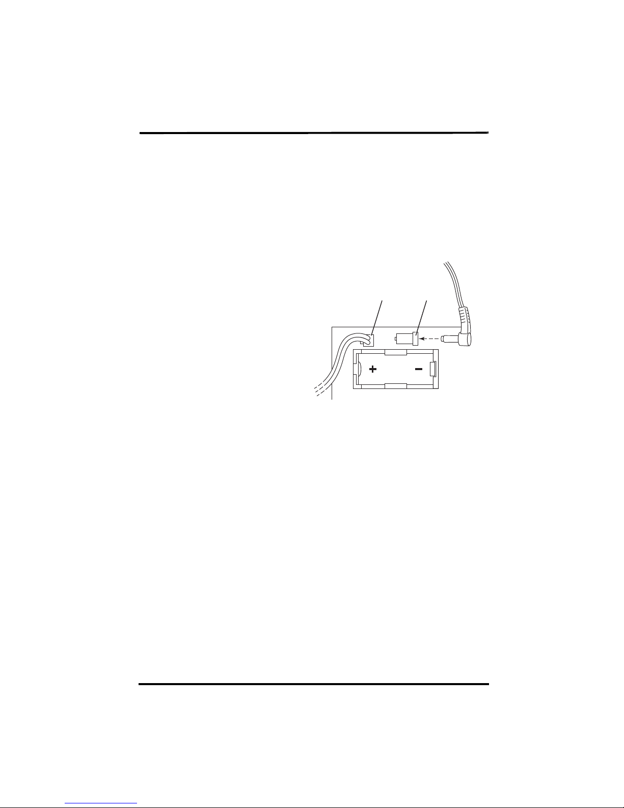
3. Insert the power adapter plug into
the repeater power jack at the top of
the board above the battery socket.
Once the AC adapter is installed,
the wireless repeater begins power-
ing the board. The repeater imme-
diately performs the Power-On Self
Test (POST) using the two LEDs
located at the bottom of the board.
The STAT (status) LED blinks red,
yellow and then green, followed by
the TX LED blinking green once,
indicating that the repeater is pow-
ered up and has passed POST.
4. Once the POST signal displays, the repeater is ready to communicate. If the repeater
has not displayed the POST light pattern, unplug the AC adapter and re-apply AC
power. If the repeater has still not performed POST and displayed the light pattern, see
“Maintenance and Troubleshooting” on page 25 for more information.
6RODU3RZHU7DE $&$GDSWHU

4
Repeater Configuration/Architecture
Vantage Pro2 Wireless Repeaters are used to enhance the transmission range and capabil-
ities between a station, or multiple stations, and a console. A repeater receives signals
transmitted from a Vantage Pro2 station and retransmits it to a console, wireless Vantage
Pro2 Envoy, or another repeater. Depending on transmission distance, one repeater or
several repeaters can be used to collect and retransmit weather data.
This section describes some of the Vantage Pro2 transmission situations and station net-
works in which a repeater or set of repeaters can be used.
Repeater Architecture
Two general types of repeater configurations are discussed in this chapter: Single
Repeater configurations and Advanced Repeater configurations. A single repeater con-
figuration describes any situation in which one repeater is needed to transmit a signal
from one station to one receiver (console or Envoy).
Advanced repeater configuration describes any architecture where one or more stations
and one or more repeaters are combined to form a network of transmitters. For example,
if a station is placed some distance away from a console that a single repeater is not in
range of the console, multiple repeaters can be set up across the distance to transmit
weather data to the console, in a chain. Another advanced repeater configuration might
involve one or more stations transmitting to a repeater. It is also possible to create a net-
work using a combination of multiple transmitters and repeaters.
Note: All range estimates used in the examples below are based on the maximum “line of sight” transmis-
sion distance of 1000’. Transmission distance vary based on location and site limitations.
Refer to the repeater configuration section that best suits the intended repeater applica-
tion.
Single Repeater Configuration
Use a single repeater as part of a single station, single console setup when the distance
between that station and the console is greater than the maximum transmission distance
of 1000' but less than 2000', where one station can not successfully communicate with a
receiver.

5
The block diagram below shows the typical single repeater configuration:
This configuration allows for greater distances between a station and a console. The dis-
tance gained between the station and the console is up to 1000' more.
Note: The maximum distance allowable ina single repeater configuration is 2000’. If thedistance between
a station and a console is more than 2000’, see “Multiple Repeater (Daisy-Chain) Configuration”
below. If more than one station exists, see “Multiple Stations, One Repeater Configuration” on
page 6.
Advanced Repeater Configurations
Multiple Repeater (Daisy-Chain) Configuration
More than one repeater should be used to transmit weather information from station to a
console if the distance between the station and console is greater than 2000' (a single
repeater configuration distance), or if they are not in line of sight of each other. A multi-
ple repeater or daisy-chain configuration can create a transmission distance of up to 9000'
using the maximum of eight repeaters.
Note: The limit of eight repeaters is based on the number of unique repeater IDs available in a network.
The block diagram below shows the typical daisy chain configuration:
Any Vantage Pro2
Station
Repeater
1
1
1
1
1
AOR
Vantage Pro2
Console/Receiver
Weather Envoy
A
A
A
1A
Repeater
1 1
1
C
Repeater
1B
1
Any Vantage Pro2
Station
Repeater
1
1A
Vantage Pro2
Console/Receiver
ABC
C

6
The above diagram displays an example daisy chain configuration of one station and
three repeaters, creating a total line of sight transmission distance of 4000'. This configu-
ration allows more flexibility between a station and a console. The distance gained
between the station and the console is up to 1000' more per each repeater that is added to
the network.
Multiple Stations, One Repeater Configuration
One repeater can be used to transmit weather information from multiple stations to a con-
sole if the repeater is within a 1000' line-of-sight radius of each station. The repeater can
transmit and repeat weather data from up to 8 different weather stations.
The block diagram below shows the multiple station configuration:
The above diagram displays an example multiple transmitter configuration of three sta-
tions and one repeater, with the repeater within a 1000' line-of-sight distance of all three
stations and the console, giving an effective distance of up to 2000' for a complete config-
uration.
The repeater can receive signals from up to eight stations/transmitters of any type. How-
ever, there are some limitations as to how many and what type of transmitters the receiver
Temp/Humidity
Station
or
Temperature
Station
Leaf & Soil Moisture
Station
or
Anemometer
Transmitter Kit
Vantage Pro2
Station
Repeater
1
2
3
2
1
3
A2
1
3
2
1
3
Vantage Pro2
Console/Receiver
A
A

7
can listen to. The table below lists the maximum number of transmitters allowable for
one receiver:
Maximum Number of Transmitters in a network with one receiver
*Allowable only if the stations are used in combination, not two of the same kind. For example, A netowrk can
have both a Leaf Wetness/Temperature station and a Soil Moisture/Temperature station, but not two Soil Mois-
ture/Temperature stations.
Combination Network Configurations
Given the flexibility of the repeater to listen to more than one station and to transmit to
other repeaters, both stations and repeaters can be set up to create a variety of transmitter
networks to transmit to one receiver. Up to eight repeaters and eight stations can be con-
figured to transmit to one receiver in a variety of ways.
Note: The limit of eight stations and eight repeaters is based on the number of unique stations identifica-
tions available in a network.
The block diagram below shows a sample combination network:
The above diagram displays an example multiple transmitter/repeater configuration of
five stations and three repeaters, with repeaters listening to stations and other repeaters,
each repeater and station must be within the 1000' line-of-sight range of a repeater.
A repeater can receive signals from up to eight stations/transmitters total, but there is also
a limit on the number of certain types of transmitters. See “Maximum Number of Trans-
mitters in a network with one receiver” on page 7 for the transmitter limitations.
Transmitter Type Maximum Number
Integrated Sensor Suite (ISS) 1
Anemometer Transmitter Kit 1
Leaf & Soil Moisture/Temperature Station* 2
Temperature Station 8
Temperature/Humidity Station 8
Temp/Humidity
Station
Leaf & Soil Moisture
Station
Vantage Pro2
Station
RepeaterRepeater
2
4
45
C3
3
B
Repeater
1
1
2
A
2
1
4
5
3
4
3
2
1
5
Vantage Pro2
Console/Receiver
Temperature
Station
Anemometer
Transmitter Kit
2
1
23
1
AB C
C
5
Este manual sirve para los siguientes modelos
1
Tabla de contenidos
Otros manuales de Reloj de repetición de DAVIS

DAVIS
DAVIS Wireless Repeater 7614 Manual de usuario

DAVIS
DAVIS Wireless Repeater 7624 Manual de usuario

DAVIS
DAVIS Wireless Repeaters for VP2 Manual de usuario

DAVIS
DAVIS Wireless Repeater 7614 Manual de usuario

DAVIS
DAVIS 7654OV Manual de usuario

DAVIS
DAVIS Wireless Repeater 7624 Manual de usuario

DAVIS
DAVIS 7626 Manual de usuario


