
Davicom DM9000A Suplemento

DM9000A
APPLICATION NOTES
Preliminary 1
Version: DM9000A-AN-V121
November 27, 2007
DM9000A
16 / 8 Bit Ethernet Controller
with General Processor Interface
Application Notes V1.21
Technical Reference Manual
Davicom Semiconductor, Inc

DM9000A
APPLICATION NOTES
Preliminary 2
Version: DM9000A-AN-V121
November 27, 2007
1INTRODUCTION.................................................................................................6
1.1 General Description..................................................................................................................6
2GENERALPROCESSOR BUS DESCRIPTION...............................................7
2.1 Typical Signal Connection with Processor Bus.........................................................................7
2.1.1 Pin Function Table.............................................................................................................8
2.1.2 Processor Parallel Bus 8/ 16-Bit Mode Setting..................................................................8
2.1.3 Command Type...................................................................................................................9
3SYSTEM HARDWARE DESIGN......................................................................10
3.1 How to Select Chip..................................................................................................................10
3.2 Strap Pins Setting....................................................................................................................10
3.3 Serial EEPROM Operation.....................................................................................................10
3.3.1 EEPROM Format.............................................................................................................11
3.4 GPIO Pins Setting...................................................................................................................15
3.5 Schematic Reference Design...................................................................................................17
3.5.1 Application Schematics for 8-Bit and 16-Bit....................................................................17
4RESETOPERATIONAND PHYPOWER-DOWN MODE...........................19
4.1 Power On Reset.......................................................................................................................19
4.2 Software Reset.........................................................................................................................19
4.3 PHY Power Down Mode.........................................................................................................19
4.3.1 GPR PHYPD Setting........................................................................................................20
4.3.2 PHY Register Setting........................................................................................................20
5HOWTO PROGRAM DM9000A......................................................................21
5.1 How to Read/ Write DM9000A Register .................................................................................21
5.2 Driver Initializing Steps..........................................................................................................22
5.3 How to Read/ Write EEPROM Data .......................................................................................23
5.3.1 HOWTO Read EEPROM Data ......................................................................................23
5.3.2 HOWTO Write EEPROM Data......................................................................................24
5.4 How to Read/ Write PHY Register ..........................................................................................26
5.4.1 HOWTO Read PHY Register..........................................................................................26
5.4.2 HOWTO Write PHY Register .........................................................................................27
5.5 How to Transmit Packets ........................................................................................................28

DM9000A
APPLICATION NOTES
Preliminary 3
Version: DM9000A-AN-V121
November 27, 2007
5.5.1 Packet Transmission.......................................................................................................28
5.5.2 To Check a Completion Flag..........................................................................................29
5.6 How to Receive Packets..........................................................................................................30
5.6.1 Receive Interrupt Service Routine..................................................................................30
5.6.2 Packet Reception............................................................................................................31
5.6.3 To Check the Packet Status and Length..........................................................................31
5.6.4 Receive the Packet's Data..............................................................................................32
6THE OTHERS.....................................................................................................33
6.1 How to transmit and receive more than 2048-byte packets.....................................................33
6.2 The performance of DM9000A................................................................................................33
6.3 WOL (Wake-up on LAN)..........................................................................................................33
6.4 IP/TCP/UDP checksums Offload............................................................................................37
6.5 AUTO-MDIX and Application.................................................................................................38

DM9000A
APPLICATION NOTES
Preliminary 4
Version: DM9000A-AN-V121
November 27, 2007
FIGURE 1.1 DM9000AINTERNALBLOCK DIAGRAM.................................................................6
FIGURE 2.1 SIGNALCONNECTION WITHAPROCESSOR INTERFACING ..............................7
FIGURE 2.2 CMD PINAND PROCESSOR INTERFACE.................................................................9
FIGURE 3.1 SCHEMATIC FOR 8-BITPROCESSOR .....................................................................17
FIGURE 3.2 SCHEMATIC FOR 16-BIT PROCESSOR ...................................................................18
FIGURE 5.1 PACKET TRANSMITTING BUFFER.........................................................................28
FIGURE 5.2 BLOCK DIAGRAM OF THE RECEIVED PACKETS................................................30
FIGURE 6.1AUTO-MDIX 10BASE-T/100BASE-TXAPPLICATION...........................................38

DM9000A
APPLICATION NOTES
Preliminary 5
Version: DM9000A-AN-V121
November 27, 2007
TABLE 2.1 PIN FUNCTION TABLE FOR PROCESSOR INTERFACE ...........................................8
TABLE 3.1 STRAPPIN CONTROLTABLE....................................................................................10
TABLE 3.2 EEPROM FORMAT IN 16-BITMODE .........................................................................11
TABLE 3.3 EEPROM FORMAT IN 8-BITMODE ...........................................................................13
TBALE 3.4 GENERAL PURPOSE CONTROLREGISTER (GPCR) TABLE.................................15
TABLE 3.5 GENERALPURPOSE REGISTER (GPR) TABLE .......................................................16

DM9000A
APPLICATION NOTES
Preliminary 6
Version: DM9000A-AN-V121
November 27, 2007
1 Introduction
1.1 General Description
The DM9000A is a fully integrated, powerful and cost-effective Fast Ethernet MAC controller
with a general processor interface, an EEPROM interface, a 10/100 PHY and 16K Byte
SRAM (13K Byte for RX FIFO and 3K Byte for TX FIFO). It is designed with low power,
single-voltage and high performance process that supports 3.3V with 5V tolerant I/O. Besides,
the DM9000A supports 8/ 16-bit processor interface to internal memory accesses for many
different processors. It is good integrated 10/100 Mbps transceiver with AUTO-MDIX and
IP/TCP/UDP-Checksum Offload.
The goal of this document is for the embedded design engineers, to implement the DM9000A
LAN chip on any processor's architecture quickly and successfully, with providing the exact
reference information and pertaining to many embedded systems. The software programming
is very simple, so users can port the software drivers to any system easily.
LED
TX+/-
RX+/-
Autonegotiation
RX Machine
TX Machine
MAC
MII
-
/
PHYceiver
Processer
Interface
Auto-
MDIX
EEPROM
Interface
Memory
Management
Internal
SRAM
&
MII Management
Control
MII Register
10 Base T
Tx Rx
100BaseTX
transceiver 100Base-TX
PCS
&Control Status
Registers
Figure 1.1 DM9000A Internal Block Diagram.

DM9000A
APPLICATION NOTES
Preliminary 7
Version: DM9000A-AN-V121
November 27, 2007
2 General Processor Bus Description
This chapter is intended to aid design engineers connecting the DM9000A device to a
micro-processor or micro-controller. The discussion will include the pin functional table, and
the individual control signals of the DM9000A involved in the connection between the device
and an associated micro-processor/ micro-controller in detail.
EEPROM
93C46/ LC46
AUOT-MDIX
Transformer RJ-45
25Mhz
CMD (32)
CS# (37)
A2
nCS
EECS (21)
EECK (20)
EEDIO (19)
DM9000A
TXO+ (7)
TXO- (8)
RXI+ (3)
RXI- (4)
X1 (44)
X2 (43)
IOR# (35)
IOW# (36)
INT (34)
PWRST# (40)
INT
nRD
nWR
SD0~SD7 (18~10)
SD8~SD15 (31~22)
D0~D7
D8~D15
Power
On
Reset
Figure 2.1 Signal Connection with a Processor Interfacing.
2.1 Signals Connection with Processor Bus
The DM9000A can interface directly with most general processors local bus such as ARM,
MIPS, Intel, TI, Motorola, NEC, and Hitachi... It is designed to suit for the implementation of
Fast Ethernet connectivity solutions to many embedded systems.

DM9000A
APPLICATION NOTES
Preliminary 8
Version: DM9000A-AN-V121
November 27, 2007
2.1.1 Pin Function Table
Note: The pins of processor parallel interface all have a pulled down resistor about 60K Ohm
internally.
Processor
Bus Signal DM9000A
Signal Pin No. I/O Description
nRD IOR# 35 I Processor READ Command
This pin is low active at default; its polarity can be modified by the
EEPROM setting.
nWR IOW# 36 I Processor WRITE Command
This pin is low active at default; its polarity can be changed by the
EEPROM setting.
nCS /
nAEN CS# 37 I Chip Select
A low active signal is used to select the DM9000A. Its polarity can be
changed by the EEPROM setting.
SD0 ~ 7 SD0 ~ 7 18,17,16
14,13,12
,11,10
I/O DATA Bus 0 ~ 7
SD8 ~ 15 SD8 ~ 15 31,29,28
27,26,25
,24,22
I/O DATA Bus 8 ~ 15 (in 16-bit mode)
CMD CMD 32 I Command Type
When low, the access of this command cycle is INDEX port
When high, the access of this command cycle is DATA port
INT INT 34 O Interrupt Request
This pin is high active and open-collected at default; its polarity and its
output type can be modified by the EEPROM setting.
Table 2.1 Pin Function Table for Processor Interface
2.1.2 8/ 16-Bit Mode Setting
There are two operation modes of DATA bus width, 8-bit or 16-bit, when access to the internal
memory in the DM9000A. These two modes are selected by the strap pin 21 EECS shown the
following table:
EECS (pin 21) DATAwidth
0 16-bit
1 8-bit
Where, "1" means pull-high with the 10K Ohm resistor, and "0" means floating (default).
The status of DATAwidth operation mode can be examined from Bit [7] of ISR REG. FEH,
ISR (REG. FEH) IOMODE (DATAwidth)
Bit [7] Operation
0 16-bit mode
1 8-bit mode
DM9000A
APPLICATION NOTES
Preliminary 9
Version: DM9000A-AN-V121
November 27, 2007
2.1.3 Command Type
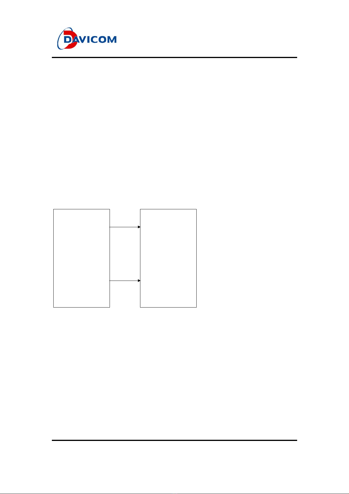
In the DM9000A, there are only two registers, named INDEX port and DATA port, which can
be accessed directly. These two ports are distinguished by the CMD pin in the access
command cycle. When CMD is low in command cycle, INDEX port is accessed; otherwise,
when CMD is high, DATAport is accessed.
All of these control and status registers in the DM9000A are accessed indirectly by the
INDEX/ DATA ports. The command sequence to access the specified control/ status register
is: firstly, to write the register’s address into INDEX port, then read/ write their data through
DATA port. The following diagram (Figure 2.2) is an example for the DM9000A CMD pin
connected to an embedded system.
The DM9000A device INDEX port
= nCS address + 0x0
The DM9000A device DATA port
= nCS address + 0x4
DM9000AProcessor
SA2
nCS
CMD
CS
Figure 2.2 CMD Pin and Processor Interface.

DM9000A
APPLICATION NOTES
Preliminary 10
Version: DM9000A-AN-V121
November 27, 2007
3 System Hardware Design
3.1 How to Select Chip
In the command cycle, the DM9000A is accessed by CS pin cooperated with IOR or IOW pins.
These pins are low active at default, while their polarity can be modified by EEPROM setting
to suit for the application of various processor types.
Both of CS pin and IOW/ IOR pin should be active to write/ read the value into INDEX port or
DATAport. So, if the IOW and IOR signals in the system are only used by the DM9000A, the
CS pin can be forced to the active logic level to simplify the system design.
3.2 Strap Pins Setting
The DM9000Aprovides the following strap pins:
Strap pins control list:
Pin Name Strap Description
20 EECK INT Polarity Type 0: INT active High
1: INT active Low
21 EECS DATA Bus Width 0: DATA 16-bit mode
1: DATA 8-bit mode
25 GP6 INT Output Type available in 8-bit modeonly
0: INT Force-Output mode
1: INT Open-Drain mode
Table 3.1 Strap Pin Control Table
Note: "1" means pull-high with the 10K Ohm resistor, and "0" means floating (default).
Tabla de contenidos
Otros manuales de Controladores de Davicom


