Danley DSA125X4 Manual de usuario

INSTALLATION GUIDE/USER MANUAL
DSA125X4
Rev. 20220706

Technical and Safety Notices
Please read the following important technical, safety
and environmental notices before installing and using
your amplier.
Technical Notices
All reasonable design and engineering steps have been taken
to ensure that these ampliers always perform satisfactorily
in their intended application and environment and will provide
appropriate levels of support to ensure that all reasonable
customer needs and expectations are met. Such support
however is contingent on the following provisions.
1. These ampliers are Class-I products and should be installed
with a mains cable including the required earth connection to
comply with the Safety Class-I.
2. These ampliers should always be installed by competent
and qualied personnel. Amplier damage or failure caused
by installation or operational errors may invalidate support,
warranty or guarantees of performance.
3. These ampliers are not suitable for use in locations where
they may be accessible to minors.
4. These ampliers are intended to be used specically for the
amplication of audio signals and for connection to moving-coil
loudspeaker systems. Use of these ampliers for amplication
of signals outside the audio band (20Hz to 20kHz) or to
drive transducers other than moving-coil loudspeakers may
invalidate support, warranty or guarantees of performance.
5. These ampliers should only be used within professionally
installed and congured audio systems comprising input
and output ancillary equipments that is known to be of an
appropriate level of performance and in good operating
condition. Any damage to, or unsatisfactory performance from,
these ampliers caused by inadequate or failed input or output
ancillaries may invalidate support, warranty or guarantees of
performance.
6. These ampliers are intended to be installed and operated
indoor in a controlled environment (pollution degree, PD2)
within an ambient temperature range of 0°C to 40°C. These
ampliers are not intended for use above 2000 meters above
sea level. Ampliers installed or operated in environments
outside these limits may invalidate support, warranty or
guarantees of performance.
7. Specic warranty terms are the responsibility of the amplier
re-seller.
Safety and Environmental Notices
Note: The intent of the lightning ash with arrowhead symbol
in a triangle is to alert the user to the presence of uninsulated
“dangerous” voltage within the product’s enclosure that may be of
sufcient magnitude to constitute a risk of electric shock to humans.
Note: The intent of the exclamation point within an equilateral
triangle is to alert the user to the presence of important safety, and
operating and maintenance instructions in this manual.
WARNING! TO PREVENT FIRE OR ELECTRIC SHOCK,
DO NOT EXPOSE THIS EQUIPMENT TO RAIN OR
MOISTURE.
Ambient Temperature Note: If this equipment is
operated in a conned or multiple rack installation, the
internal ambient operating temperature may exceed
the external ambient temperature.
It is important to ensure in these
circumstances that the published
maximum operating temperature for the
equipment is not exceeded.
Reduced Air Flow: Ensure that rack or
other closed installation does not restrict
the cooling airow required for safe and
reliable operation of the equipment.

Technical and Safety Notices
Important Safety Instructions
1. Read these instructions.
2. Keep these instructions.
3. Heed all warnings.
4. Follow all instructions.
5. Do not use this apparatus near water.
6. Do not submerge the equipment in water or liquids.
7. Do not use any aerosol spray, cleaner, disinfectant or
fumigant on, near or into the equipment.
8. Clean only with a dry cloth.
9. Do not block any ventilation opening. Install in accordance
with the manufacturer’s instructions.
10. Do not install near any heat sources such as radiators, heat
registers, stoves, or other apparatus (including ampliers)
that produce heat.
11. To reduce the risk of electrical shock, the power cord shall
be connected to a mains socket outlet with a protective
earthing connection.
12. Do not defeat the safety purpose of the polarized or
grounding type plug. A polarized plug has two blades with
one wider than the other. A grounding type plug has two
blades and a third grounding prong. The wide blade or the
third prong are provided for your safety. If the provided
plug does not t into your outlet, consult an electrician for
replacement of the obsolete outlet.
13. Protect the power cord from being walked on or pinched
particularly at plugs, convenience receptacles, and the
point where they exit from the apparatus.
14. Do not unplug the unit by pulling on the cord, use the plug.
15. Only use attachments/accessories specied by the
manufacturer.
16. Unplug this apparatus during lightning storms or when
unused for long periods of time.
17. Refer all servicing to qualied service personnel. Servicing
is required when the apparatus has been damaged in any
way, such as power supply cord or plug is damaged, liquid
has been spilled or objects have fallen into the apparatus,
the apparatus has been exposed to rain or moisture, does
not operate normally, or has been dropped.
18. The appliance coupler, or the AC Mains plug, is the AC
mains disconnect device and shall remain readily accessible
after installation.
19. Adhere to all applicable, local codes.
20. Consult a licensed, professional engineer when any
doubt or questions arise regarding a physical equipment
installation.
Environmental Statement
This product complies with international
directives, including but not limited to the
Restriction of Hazardous Substances (RoHS)
in electrical and electronic equipment, the
Registration, Evaluation, Authorization and
restriction of Chemicals (REACH) and the
disposal of Waste Electrical and Electronic Equipment (WEEE).
Consult your local waste disposal authority for guidance on
how properly to recycle or dispose of this product.

Introduction and Overview
1. Introduction
Danley DSA power ampliers have been designed
to provide congurable, consistent and reliable high
performance audio power amplication for residential,
commercial and entertainment applications. Please
read this manual fully before installing and using an
amplier. If you have any questions regarding amplier
conguration, installation or operation please contact
the appropriate customer support portal.
Following this introduction, the manual is divided into sections
covering the following topics:
• 2. Overview
• 3. Carton Contents
• 4. Installation
• 5. Conguration
• 6. Connections
• 7. Operation
• 8. Specications
2. Amplier Overview
Danley DSA125X4 ampliers are half rack width, 1U format
power ampliers that can drive both conventional low
impedance (Lo-Z, 4Ω to 16Ω) loudspeakers and high impedance
(Hi-Z, 70V/100V) transformer coupled loudspeakers. They
provide four analog inputs, one stereo S/PDIF digital input, and
either two or four outputs (Lo-Z mode), or one or two outputs
(Hi-Z mode). Danley DSA ampliers also incorporate automatic
power sharing technology that enables power to be shared
proportionately as required between pairs of outputs in Lo-Z
mode. Danley DSA amplier model output channel counts and
power outputs are as follows:
DSA125X4
Mode Channels Max Rated Output per Channel
Lo-Z Four 125 Watts
Hi-Z Two 250 Watts

Introduction and Overview
2.1 Connections
Danley DSA signal input and output connections are
accomplished via RCA Phono and Euroblock style connectors.
A GPIO (General Purpose In/Out) Euroblock connector enables
some amplier functions to be controlled, and wireless or RJ45
socket Ethernet network connection options are also provided.
Danley DSA ampliers have no mains power switch and are
operational as soon as mains power is connected via the IEC
60320 mains socket.
2.2 Network Features
Danley DSA ampliers are TCP/IP network connected devices
that require a wired or wireless network connection to access
their conguration menus. The conguration menus are
accessed via the Danley DSA Control web app interface and
cover Input, Zone, Output and General Settings functions. The
conguration menus are fully described in Section 4 of this
manual.
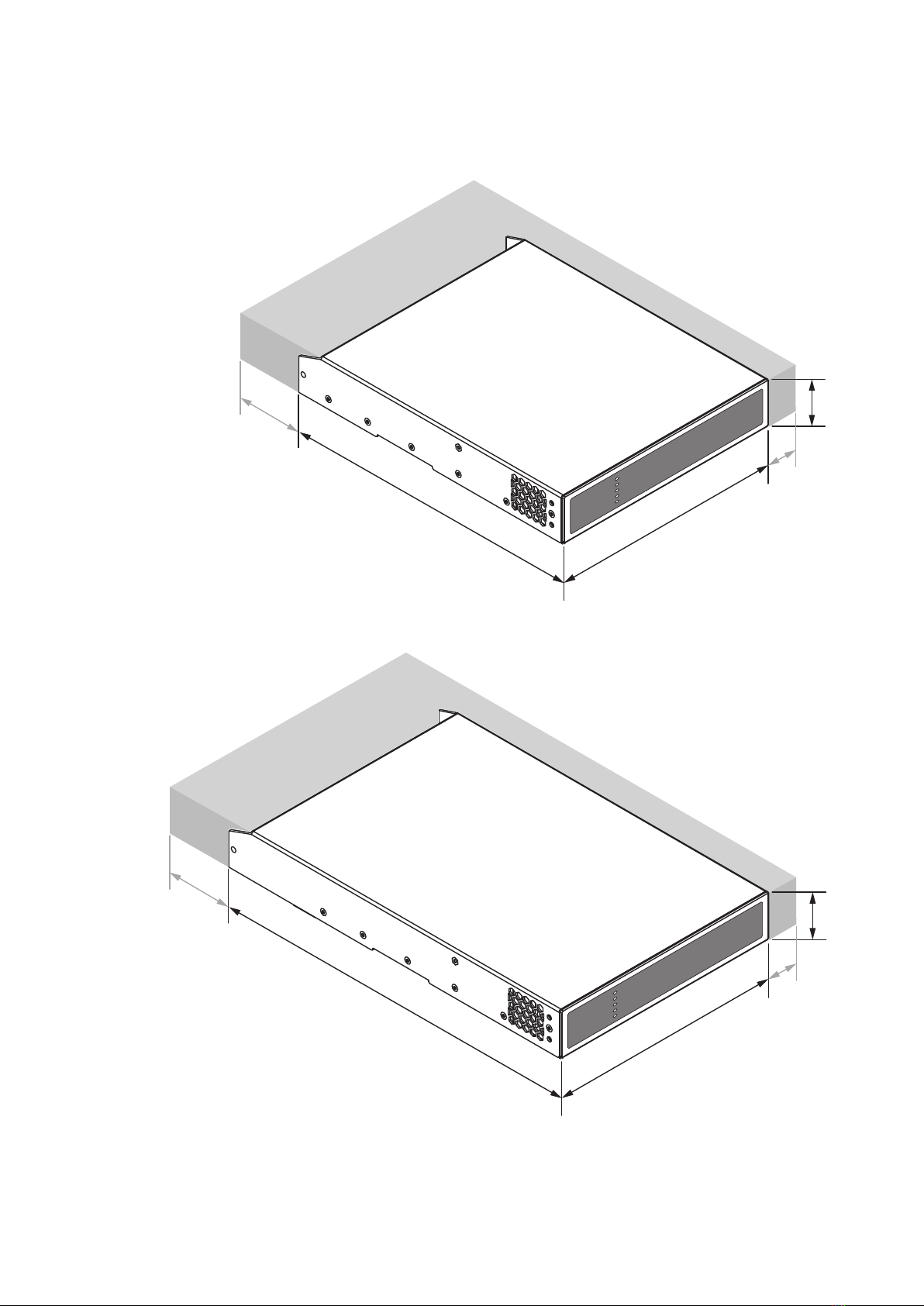
2.3 Dimensions
Danley DSA amplier dimensions and features are illustrated
in Diagrams 1a and 1b. The ampliers are primarily intended
for installation in an equipment rack but can also be under-desk
or wall mounted, or used free standing. They are fan-cooled
and must be installed such that ventilation apertures are not
obstructed.
2.4 Firmware
This manual describes the features, functions and user
interface of Danley DSA ampliers running Firmware Version
1.2.0.
It is strongly recommended that the rmware version
installed in the amplier in use is checked initially, and
regularly thereafter. If updated rmware is available,
the amplier should be updated as a priority.
The rmware installed in the amplier can be identied and
updated by selecting the Device option in the Control web
app Settings Menu. Firmware versions can be checked, and
rmware downloaded, from the Danley DSA website:
3. Carton Contents
Danley DSA ampliers are shipped in a cardboard carton
containing the amplier unit, a mains cable appropriate for the
sales territory, an accessory pack, and a document pack. The full
contents is listed below.
• Amplier unit
• Mains power cable
• Input connector x 2
• GPIO socket connector
• Output connector x 1 or 2
• Adhesive rubber feet x 4
• Document pack
Overview
Diagram 1b
Danley DSA four channel amplier dimensions.
(Shaded area denes ventilation space.)
Diagram 1a
Danley DSA two channel amplier dimensions.
(Shaded area denes ventilation space.)
44 mm
1.7 in
44 mm
1.7 in
220 mm
8.7 in
220 mm
8.7 in
213 mm
8.4 in
80 mm
3.1 in
80 mm
3.1 in
319 mm
12.6 in
25 mm
1.0 in
25 mm
1.0 in
Installation
4. Installation
Note: The rack mounting and desk/wall mounting components
described and illustrated in Sections 4.1 to 4.3 are not supplied with
Danley DSA ampliers but are available to purchase as accessories.
Contact your amplier re-seller for more information.
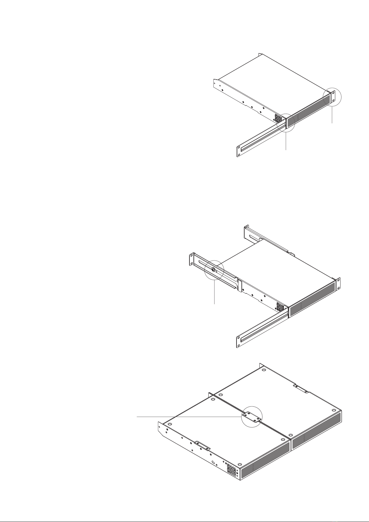
4.1 Danley DSA Mounting
The Danley DSA ampliers are shipped without rack mount
hardware attached but can be congured for rack installation
using one standard rack ‘ear’ and one half-rack extension piece
as illustrated in Diagram 3a. The installation and equipment
rack should be congured to provide appropriate ventilation
airow space around the sides and rear of the amplier as
illustrated in as illustrated in Diagram 1a. Ventilation airow
space of at least 25 mm (1 in) should be maintained along at
least one side of the amplier at all times. Ventilation apertures
are also located on the rear panel of the amplier and must not
be obstructed. It is important to retain at least 80 mm (3.1 in)
free space for airow behind the amplier rear panel.
In addition to rack mount ears, optional rack mount rear
support hardware is available and can be attached to the
amplier. Rear support hardware may be appropriate if
the amplier is to be used in a mobile rack or potentially be
subject to signicant movement. Diagram 3b illustrates the
use of rack mount rear support hardware.
Multiple Danley DSA ampliers can also be mechanically
connected using accessory connecting plates. Diagram 3c
illustrates the use of connecting plates.
Diagram 3a
Danley DSA
Rack Ear + Half-rack Extension.
Diagram 3b
Danley DSA
Rack Support hardware. 2 positions.
Rack Ear +
2 x M4 x 8
countersunk
Half-rack Extension +
2 x M4 x 8 countersunk
Rear Support + Button +
1 x M4 x 8
Connection Plate +
4 x M3 x 6 countersunk
Diagram 3c
2 x Danley DSA with Connection Plate. 2
positions

Installation
Diagram 4a
Danley DSA
with desk/wall Mounting Plate and adhesive feet.
2 positions and 4 positions.
Diagram 4b
Danley DSA
wall and under-desk mount.
4.2 Free-standing
If not installed in an equipment rack, Danley DSA ampliers can
be placed free-standing on a at surface. Adhesive rubber feet
are supplied for this purpose.
Danley DSA ampliers can also be attached to the
underside of desks or wall mounted using connecting
plate hardware. The adhesive rubber feet should
also be used in these circumstances to minimise
the possibility of vibration between the amplier
and mounting surface. Wall and desk mounting is
illustrated in Diagrams 4a and 4b.
It is important in any free standing installation that
airow through the amplier’s side panel mounted
fans and rear panel ventilation apertures is not
compromised by adjacent items. At least 80mm of
free space behind the amplier and 25mm along at
least one side should be retained at all times. Mounting Plate +
2 x M3 x 6 countersunk
Adhesive Foot
4 positions

Conguration
5. Conguration
Before making input, output and GPIO connections,
an initial Danley DSA amplier conguration should
be established. It is particularly important that the
amplier output format is congured appropriately for
the speakers that are to be connected.
Conguration requires that Danley DSA ampliers are
connected to mains power and network services. These
connections are described in the following two sections.
5.1 Mains Power Connection
Danley DSA ampliers incorporate a power factor corrected
power supply and can be used with mains input voltage from
100V AC to 240V AC, 50/60Hz. Use the mains cable supplied
with the amplier and connect it to a switched mains supply.
Danley DSA ampliers have no mains power switch and are
operational as soon as mains power is connected.
5.2 Network Services
Danley DSA ampliers are congured via a web page
interface called Danley DSA Control. Before the
conguration menus can be accessed, Danley DSA
ampliers must be connected to the same TCP/IP
network as the computer or mobile device that is to be
used for conguration access.
5.2.1 Wired (Ethernet) Network Connection
To connect a Danley DSA amplier to a TCP/IP network using a
wired connection (Ethernet) follow the steps below.
1. Use an Ethernet cable to connect the Danley DSA amplier
rear panel Network Control socket to a free socket on a
network router or switch, or directly to an Ethernet equipped
laptop or desktop computer.
2. Connect the Danley DSA amplier to mains power using
the supplied mains cable. Wait for the front panel Network
indicator to illuminate green to indicate that the amplier has
network connectivity.
3. The Danley DSA amplier default LAN IP address is
192.168.64.100. Congure the laptop or desktop computer
for a xed IP address in the same IP range; eg. 192.168.64.10,
with Subnet mask of 255.255.255.0 (or prex 24) and set the
Gateway to 192.168.64.1.
4. Open a laptop or desktop web browser and enter the
address http://192.168.64.100. The Danley DSA Control Web
App interface will open to enable amplier conguration as
required.
Note: Danley DSA ampliers can be congured to use DHCP for
network connection if required. However, if a Danley DSA amplier
using DHCP is power cycled, it is possible that the TCP/IP network
router will assign it a different IP address, leaving its conguration
page inaccessible via the previous address. If this occurs, a network
scanning app can be used to identify the new IP address. DHCP and
Fixed IP address option settings can be found in the Settings Tab
menu described in Section 5.3.
5.2.2 Wireless (WiFi) Network Connection
To connect a Danley DSA amplier to a TCP/IP network using a
wireless connection (WiFi) follow the steps below.
1. With the Danley DSA amplier connected to mains power,
wait for the front panel WiFi indicator to illuminate green.
2. Use a mobile, laptop or desktop device to search for available
WiFi networks. Connect to, Danley DSA (product serial
number)’ using the password, ‘password’. The amplier serial
number can be found on its rear panel.
3. Open a computer or mobile device web browser and enter
the IP address: 192.168.4.1. The Danley DSA Control Web
App interface will open to enable amplier conguration as
required.
4. Select the Web App Settings Tab followed by WiFi > WiFi
Mode > Client to congure the amplier to connect to the
required WiFI network. The WiFi network name and password
will be required.
It is strongly recommended that the Danley DSA amplier
Access Point WiFi password is changed following initial
wireless connection.

Conguration
5.3.1 Input Tab
The Input Tab provides naming, mono/stereo selection,
sensitivity, and gain trim for each amplier input channel. An
internal pink noise source, provided for system testing and set
up, can also enabled or disabled, and adjusted for gain via the
Input Tab. Diagram 5b illustrates the Input Tab.
Diagram 5a
Conguration Dashboard display
(two output amplier model shown)
Diagram 5b
Input Tab display
(two inputs only shown)
Input name - type to edit
Select mono or stereo
Select input sensitivity option
Adjust input gain
Adjust zone volume
Adjust zone volume
Note: When adjusting input gain, the input level display should
remain green. If it displays red, the input gain should be reduced.
5.3 Conguration Menus
Opening a web browser that is network connected to a Danley
DSA amplier initially displays the Danley DSA Control Web
App Dashboard illustrated in Diagram 5a. The Dashboard is the
‘home’ page from which all other conguration options can be
accessed.
The Dashboard displays the amplier status, output zones and
the conguration menu tabs. It also enables immediate access
to zone volume control The functions available under each
conguration menu tab are described in the following sections.
Tabla de contenidos
Otros manuales de Amplificador de Danley


