D.W. Fearn VT-4 Manual de usuario
Operating Instructions
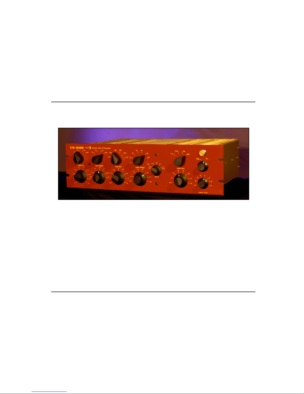
D.W. FEARN
VT-4 Vacuum Tube LC Equalizer

HOW TO CONTACT US:
Telephone: 610-793-2526
Fax: 610-793-1479
Mail: P.O. Box 57, Pocopson, PA 19366 U.S.A.
Shipping Address: 182 Bragg Hill Road, West Chester, PA 19382 U.S.A.
e-mail: dwfearn@dwfearn.com
Web: www.dwfearn.com

D.W. Fearn shall not be liable for technical or editorial errors or omissions in this
manual, nor for incidental or consequential damages resulting from the use of this
material.
This instruction manual contains information protected by copyright. No part of this
manual may be photocopied or reproduced in any form without prior written consent
from D.W. Fearn.
Copyright © 2000 D.W. Fearn & Associates

D.W. Fearn VT-4 Vacuum Tube LC Equalizer 5
TABLE OF CONTENTS
Warranty.................................................................................7
Specifications ........................................................................9
Features ...............................................................................11
History of the VT-4 ..............................................................13
Description ...........................................................................15
Installation ..........................................................................17
Operation .............................................................................19
Theory .................................................................................21
Maintenance ........................................................................23

LIMITED 5-YEAR WARRANTY
During the warranty period, D.W. Fearn will, at no additional charge, repair or replace
defective parts with new parts.
This warranty does not extend to any VT-4 that has been damaged or rendered defec-
tive as a result of accident, misuse, or abuse; by the use of parts not manufactured or
supplied by D.W. Fearn; or by unauthorized modification of the VT-4. Vacuum tubes
are excepted from the 5-year warranty, but are warranted for 90 days from date of
purchase.
Except as expressly set forth in this Warranty, D.W. Fearn makes no other warranties,
express or implied, including any implied warranty of merchantability and fitness for
a particular purpose.
D.W. Fearn VT-4 Vacuum Tube LC Equalizer 7

D.W. Fearn VT-4 Vacuum Tube LC Equalizer 9
Input 600 ohms
Input Load
Impedance 40k ohms
Minimum Input
Level -20 dBm nominal
Maximum Input
Level @ 20 cps +25 dB
Gain 0 dB
Frequency
Response ± 0.5 dB 20 cps to 20 kc
-3 dB @ 0.5 cps & 80 kc
THD + Noise <0.10% 20 cps to 20 kc
Intermodulation
Distortion SMPTE: <0.80%
Signal to
Noise Ratio 82 dB minimum
Output low-Z, transformer balanced
Maximum
Output Level +22 dBm unterminated
Power
Requirements 100, 120, or 220 VAC
50/60Hz, 25 W
Dimensions 19” (48.26cm) W
5.25” (13.34cm) H
9” (22.86cm) D (VT-2 13” 22.9cm)
Weight 14 lbs (6.35 kg)
SPECIFICATIONS
Note: Throughout this manual, frequency is specified in cps (cycles per second) or kc
(kilocycles per second). These units of measurement correspond to Hz and kHz respec-
tively. Specifications subject to change without notice
(All measurements made with +4dBm in and out, Eq switched in
but all controls set to flat.)

D.W. Fearn VT-4 Vacuum Tube LC Equalizer 11
EQ FEATURES
(All controls are independent and can be used in any combination)
Low Cut at 30, 40, 100, or 400 Hz,
0 to -18 dB shelving in 2 dB steps
Low Boost at 20, 40, 60, or 140 Hz,
0 to 12 dB shelving in 2 dB steps
Mid Cut at 200, 300, 400, 500, 600,
or 700 Hz, 0 to -16 dB in 2 dB steps
High Boost at 2, 3, 4, 5, 8, 10, 12, or 16 kHz,
0 to 14 dB in 2 dB steps
High Bandwidth Q of 0.6, 0.8, 1.0, 1.4, or 1.7
High Frequency Cut at 1.7, 4, 10, or 28 kHz,
0 to -14 dB shelving in 2 dB steps
Gain adjustable from -9 to +9 dB,
referenced to +4 dBm, in 3 dB steps
Note: Throughout this manual, frequency is specified in cps (cycles per second) or kc
(kilocycles per second). These units of measurement correspond to Hz and kHz respec-
tively. Specifications subject to change without notice

D.W. Fearn VT-4 Vacuum Tube LC Equalizer 13
HISTORY OF THE VT-4
Throughout my career in recording, there have always been a few equalizers that stood out as being
exceptional. Among my favorites are the 1970s-era Neve input-strip eqs, and the Trident CB9066 para-
metric. I began my equalizer development project by first building a series of test circuits, using all
the various tone-modification techniques. After listening to a wide variety of equalization circuits, it
was obvious to me that the passive inductor-capacitor (LC) circuit was the one that sounded the most
musical and natural to me.
In thinking about how I use equalization, I realized that having simultaneous boost and cut at the low
and end frequencies was often very useful. For mid-frequencies, I found that I always cut, usually
around 400 Hz, and never had any reason to boost in that range. If I were using a parametric equal-
izer, I invariably tended to use the low-Q (broadest) settings, and if I had a choice between shelving or
peaking on the high and low end, I almost always prefered the shelving curve.
So the VT-4 was designed around those preferences -- low-Q curves, shelving, with simultaneous boost
and cut, mid-range cut but not boost, and using passive LC circuitry.
The amplification stages would be vacuum tube, and since the VT-1/VT-2 mic preamps have had such
a gratifying acceptance in the world of recording, it was important to preserve the same sonic charac-
teristics that distinquished the preamps. I decided to try the Svetlana 6N1P dual triode, and was pleas-
antly surprised to find that it is a wonderful-sounding tube, with many of the same sonic characteris-
tics as the 6072A used in my preamps. The active tube circuitry fell into place with relatively little
effort. Now it was time to make the equalization circuitry work the way I wanted.
To start, I used the filter design tables developed by Bell Labs in the 1930s. That got the project off
the ground and it was starting to sound pretty good. For several months, I listened to a variety of music
through a prototype equalizer while I was working on other things, and gradually narrowed-in on what
sounded really good and what didn’t. I would frequently have a box of capacitors and clip leads next
to the prototype and often clipped-in a different value here or there and continued listening.
Eventually, the final frequencies, curves, control operation, etc. was determined. To this day, I have
only a vague idea of what the actual curves look like. Equalizers, like all audio equipment, should
please your ears, not your test equipment.
My experience with Jensen Transformers Inc. was so positive that I knew from the beginning that I
would utilize their products. The first couple of prototypes used inductors that I wound myself, but for
production units more-consistent inductors would be necessary. Jensen agreed to manufacture the
necessary inductors to my specifications, and the quality of the parts is astounding.

D.W. Fearn VT-4 Vacuum Tube LC Equalizer 15
DESCRIPTION
The Model VT-4 Vacuum Tube LC Equalizer is designed to provide recording professionals with a son-
ically superior outboard processing device. It is typically used in sound recording studios for modify-
ing the frequency response characterisics of an individual track. A pair of VT-4s can be used to
process a stereo mix with precise matching between units.
It is designed for use in the professional recording environment. It accepts all standard low-impedance
(nominally 600 ohm) line-level (nominally +4 dBm) signals. The output is line-level (+4 dBm) low-
impedance, transformer-isolated and designed to feed bridging inputs. It is built to sound great for a
long time, with top quality parts used throughout; all the transformers, inductors and many other com-
ponents are custom-made for the VT-4.
All power supplies are solid state and fully regulated. All rotary controls use high-quality silver-contact
switches for precise repeatability and matching between units.
Much of the circuitry for the VT-4 is based on the highly-successful D.W. Fearn VT-1 and VT-2 Vacuum
Tube Microphone Preamplifiers. Since line-level signals are utilized in the VT-4, Class-A Svetlana
6N1P dual triodes are used for all amplifier stages. The input transformer, inductors in the passive
equalization circuitry, and the output transformer are custom-made for us by Jensen Transformers
Inc.
The VT-4 is not mass-produced. Each one is hand-made and meticulously tested and listened to before
shipment to the customer.
The philosophy behind the VT-4 is: use only the best components in an optimized circuit, and build it
with pride and precision. The VT-4 is designed and built to perform in your studio for decades to come.

D.W. Fearn VT-4 Vacuum Tube LC Equalizer 17
3.
INSTALLATION
The VT-4 is carefully packed for shipment and it should survive all but the most brutal
handling. If there is any damage, keep the shipping material for use during any possible
claim for damage with the shipper.
Included in the box:
1) The VT-4 Equalizer
2) Line cord
3) This instruction manual
Mounting
The VT-4 is designed for installation in a standard 19 inch rack. It requires 5.25 inches
of vertical space, but additional spacing between it and adjacent equipment is recom-
mended for adequate cooling. Ideally, a ventilated panel at least 1 rack unit high (1.25
inches) should be installed above and below the VT-4 (and around any other heat produc-
ing equipment for that matter). Be sure the bottom vent slots are not blocked. It is essen-
tial that air can flow into the bottom and out of the top of the VT-4. Equipment that runs
cool can last for a very long time.
In tight equipment enclosures, be sure there is adequate air flow. Forced air cooling will
benefit all your equipment.
The VT-4 can also be used without a rack, placed on a table, counter, or even on the
floor. Optional rubber feet are available, when requested at the time of the order.
Moderate electrical and magnetic fields in the vicinity of the VT-4 should not cause any
degradation in noise performance, due to the well-shielded construction, but proximity to
devices with motors or large power transformers (i.e. tape machines or power amps)
should be avoided.
Although the vacuum tubes in the VT-4 are selected for minimum microphonic
response, it is a good practice to avoid mounting locations that subject the VT-4 to very
high sound or vibration levels.
Tabla de contenidos
Otros manuales de Ecualizador estéreo de D.W. Fearn


