Cygnus ROV UTM Manual de usuario
Cygnus ROV UTM
Ultrasonic Thickness Gauge
Operating Manual
Covers Instrument Model: M5-ROV-ASCAN
with SD2D-DCW Probe
Doc No. Cygnus ROV UTM Operation Manual (Issue 7).docx
June 2022

Cygnus ROV UTM - Operating Manual
Page 2 of 60
Contents
1. Introduction......................................................................5
Cygnus ROV UTM...................................................................5
Register your Gauge ..............................................................6
Kit Contents..........................................................................7
Optional Items ......................................................................7
2. System Overview ..............................................................8
Subsea Instrument ................................................................8
Ultrasonic Probe ....................................................................8
P50 Probe Handler ...............................................................10
3. Connecting the System Together ....................................13
Subsea Instrument ..............................................................13
Power and Comms ............................................................13
Connecting the Ultrasonic Probe..........................................14
Securing the Cables ..........................................................15
Connecting Topside..............................................................16
4. System Operation ...........................................................17
On the deck before launching the ROV ....................................17
Taking Thickness Measurements Subsea .................................18
Surface Preparation...........................................................18
Zeroing the Probe .............................................................18
Probe Alignment ...............................................................18
Start CygLink Topside........................................................19
Taking Measurements........................................................20
Logging Measurements ......................................................23
Manual Gain Control ..........................................................24
Using the Cursors to make Direct Measurements ...................24
Using the Display Freeze....................................................25
5. Measurement Modes .......................................................27
Single Echo Mode (SE) .........................................................27
Echo-Echo Mode (EE) ...........................................................28
Multiple Echo Mode (ME).......................................................28
Auto EE/SE/ME Mode ...........................................................29
6. Measurement Settings in CygLink ...................................30
Units...............................................................................30
Measure Mode ..................................................................30

Cygnus ROV UTM - Operating Manual
Page 3 of 60
Manual Gain.....................................................................31
Velocity of Sound and Material List ......................................31
Measurement range for A-Scan Range..................................31
7. Calibration and Zero .......................................................33
Why should I Calibrate?........................................................33
Calibrating to a Known Thickness ...........................................34
Zeroing the Probe................................................................35
8. CygLink ...........................................................................37
Installing CygLink ................................................................37
Requirements...................................................................37
Upgrading........................................................................37
Installing .........................................................................37
COM Port Numbers ..............................................................38
Setting the COM Port Manually............................................38
Finding your COM Port Number ...........................................38
Connecting to the Instrument................................................39
First time USB Connection..................................................39
Connecting the Instrument to CygLink for the First Time.........40
Connecting to the Instrument Afterwards .............................41
Disconnecting from the Gauge ............................................42
Manual Connection Settings................................................42
CygLink Surveys and Data Logging.........................................43
Editing the Survey Details ..................................................44
Editing the Survey Group Details.........................................45
Producing a Survey Report Document ..................................45
Logging Measurements Directly in CygLink ..............................46
Reference and Minimum Thickness Criteria ...........................46
Pre-Set Measurement Comments List...................................46
Adding Comments or Notes to a Measurement ......................47
To Change the COM Port number assigned by Windows®...........48
Opening Device Manager....................................................48
CygLink Trouble Shooting .....................................................49
Connection Problems –USB Drivers.....................................49
Wiring Problems ...............................................................50
9. Care and Servicing ..........................................................51
Cleaning the Instrument .......................................................51
Environmental.....................................................................51
Repairs ..............................................................................51
Returning the Gauge for Servicing..........................................51
Cygnus ROV UTM - Operating Manual
Page 4 of 60
10. Technical Specifications ..................................................52
11. Table of Sound Velocities ................................................54
Reading Conversions .........................................................55
12. Recycling and Disposal (EC Countries)............................56
13. Electrical Connections.....................................................57
Power & Comms Port (Bulkhead plug).....................................57
Probe Port (Bulkhead) ..........................................................57
14. Cygnus Instruments .......................................................58
15. Warranty Information.....................................................59
16. Index ..............................................................................60
Revision History.
Issue
Date
Changes
Issue 3
06-Jun-19
SE Mode Measurement Range increased to 55mm, on
page 49.
Issue 4
17-Jul-19
Revised depth rating to 3000m (300bar)
Issue 5
04-Oct-19
Included Maximum Surface Contact Temperature to Probe
Specifications
Issue 6
03-Nov-20
Updated for change in Probe Connector (CRE).
Updated for Serial Interface (RS-232).
Issue 7
06-Jun-22
Change of product name to “Cygnus ROV UTM”
Added product registration info.

Cygnus ROV UTM - Operating Manual
Page 5 of 60
1. Introduction
Cygnus ROV UTM
The Cygnus ROV UTM –ROV Mountable Thickness Gauges are
rugged, compact instruments designed for reliable ultrasonic
thickness measurements.
The instrument is pressure rated to a maximum depth of 3000
meters sea water (300 bar). The instrument takes its power from
the ROV craft and output thickness measurement data as serial
data in RS232 format. The thickness measurement data is viewed
top-side using CygLink which can also be used to provide Data
Logging facilities and report generation.
Measurements can be displayed in Metric (mm) or Imperial (inch)
units; measurement resolution is set to 0.1mm (0.005 inch).
Crystal-controlled Calibration provides stability and accuracy. The
thickness measurement can easily be calibrated to a known
thickness or to a known Velocity of Sound.
The instruments are able to operate accurately in adverse
environmental conditions both underwater and above the sea.
The system is a solid-state electronic instrument which,
under normal operating conditions, will give many years of
active service.
Although designed for ease of operation first time users
should carefully read this manual to familiarise themselves
with the features of the instrument

Cygnus ROV UTM - Operating Manual
Page 6 of 60
Register your Gauge
Register your gauge to receive updates on gauge firmware and to
register your 3-year warranty.
Registration is quick and easy, go to this web address;
https://cygnus-instruments.com/service/product-registration/
Product Registration Link QR
Cygnus ROV UTM - Operating Manual
Page 7 of 60
Kit Contents
The Cygnus ROV UTM system is supplied as a complete kit in a
transportation case
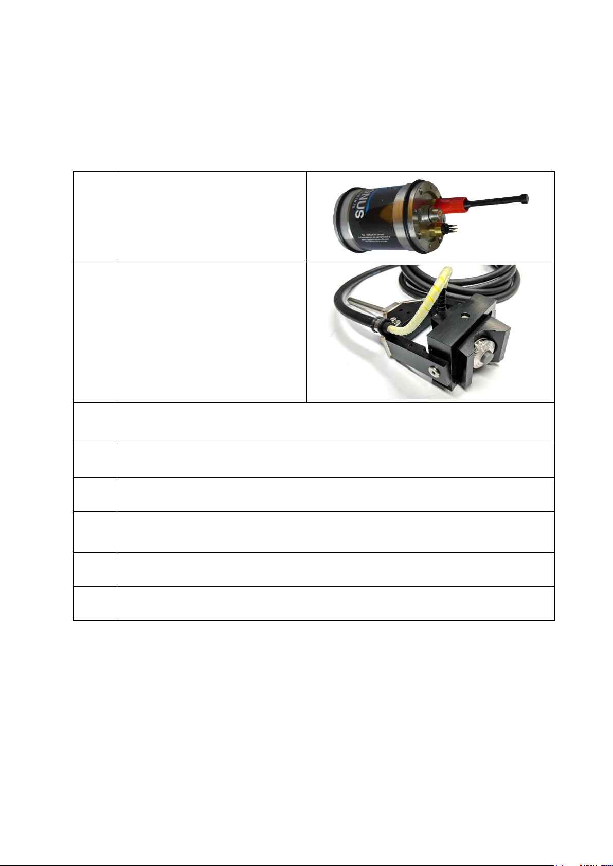
1
Cygnus ROV UTM
Subsea Instrumentation
Unit
2
SD2C-DAW 2.25 MHz
Single Element Delay
Line Probe with cable
and connector. Fitted in
P50 Probe Handler.
3
Patch cable for wiring the Cygnus ROV UTM to the ROV,
0.6m
4
Test Lead –RS-232 to USB
5
Test Block 15mm thick in 1080 Mild Steel
6
USB Flash Drive with CygLink Software and
Documentation
7
A Calibration Certificate
8
Silicon grease for lubricating connectors and O-rings
Optional Items
1. Fish tail or T-bar manipulator handle.
Cygnus ROV UTM - Operating Manual
Page 8 of 60
2. System Overview
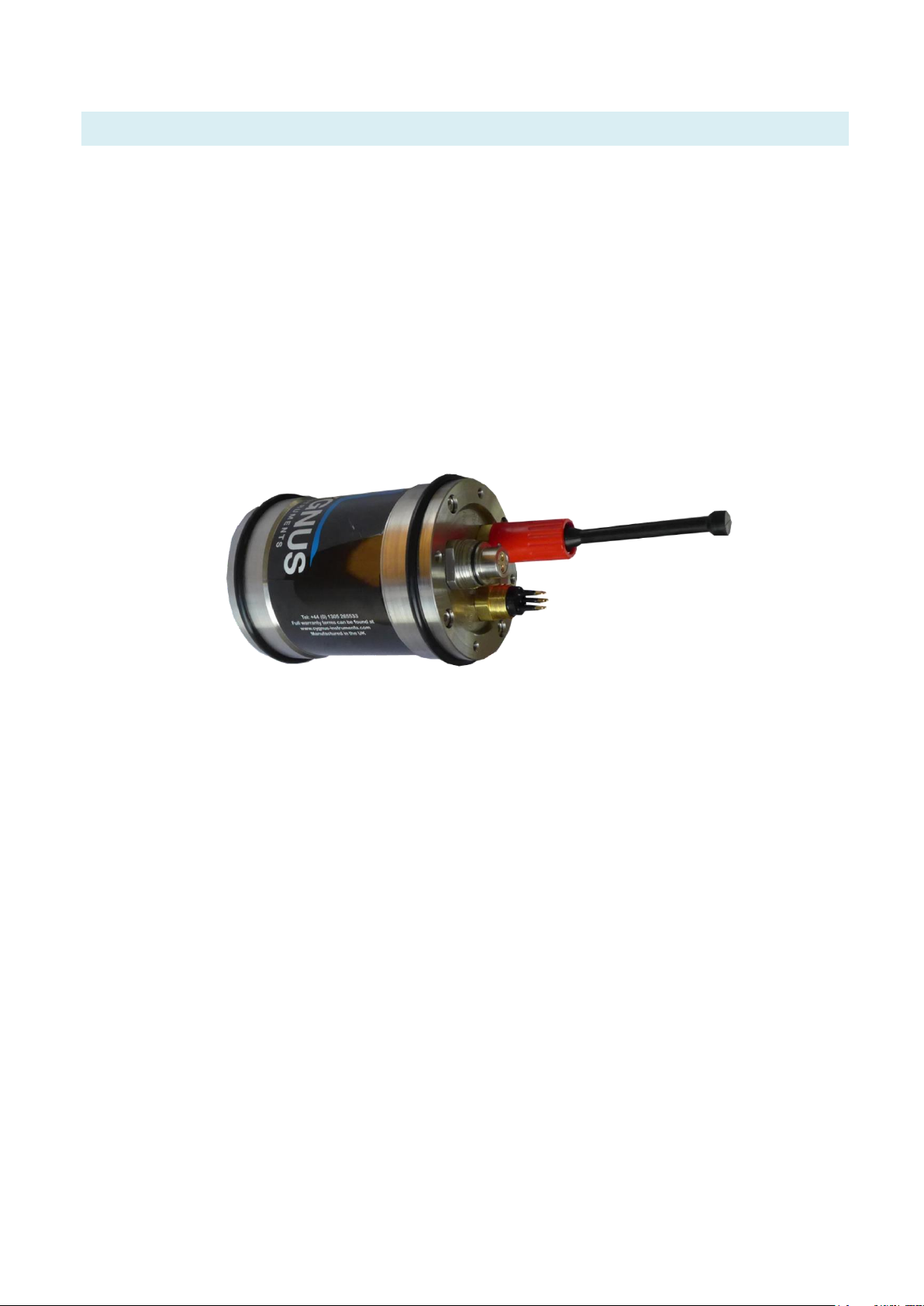
Subsea Instrument
The system is supplied ready to use. All that is required is to make
the necessary electrical connections between the subsea unit and
the ROV Craft and the top side computer.
There are no controls or display on the subsea instrument unit,
operation and calibration is performed at the surface using
CygLink software.
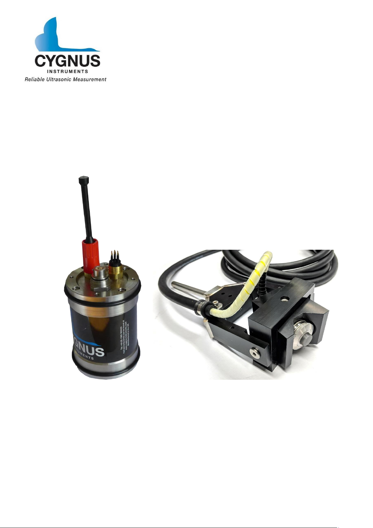
Cygnus ROV UTM Subsea Instrument Unit.
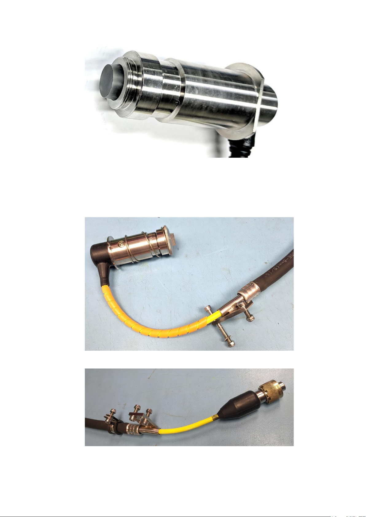
Ultrasonic Probe
The Ultrasonic Probe (model number SD2C-DCW) has a 2.25 MHz
ø13mm single element piezo-composite crystal, bonded to a
30mm long Rexolite delay line. The delay line face is ø16mm. The
delay line is bonded directly to the active element of the probe and
cannot be replaced.
The probe is fully encapsulated internally, double O-Rings seal the
delay line in the probe body.
Cygnus ROV UTM - Operating Manual
Page 9 of 60
SD2C-DCW Ultrasonic Probe.
The probe is supplied with 5m of cable, protected by an outer
reinforced air hose. Each end has a stainless steel bracket which is
attached by M5 screws and nuts.
Ultrasonic Probe Cable Mounting Bracket - P50 Probe Handler End.
Ultrasonic Probe Cable Mounting Bracket - Connector End

Cygnus ROV UTM - Operating Manual
Page 10 of 60
Connection to the subsea unit is by a multi-pin connector secured
by a brass threaded collar.
The instrument is designed only to be used with ultrasonic
probes supplied by Cygnus Instruments.
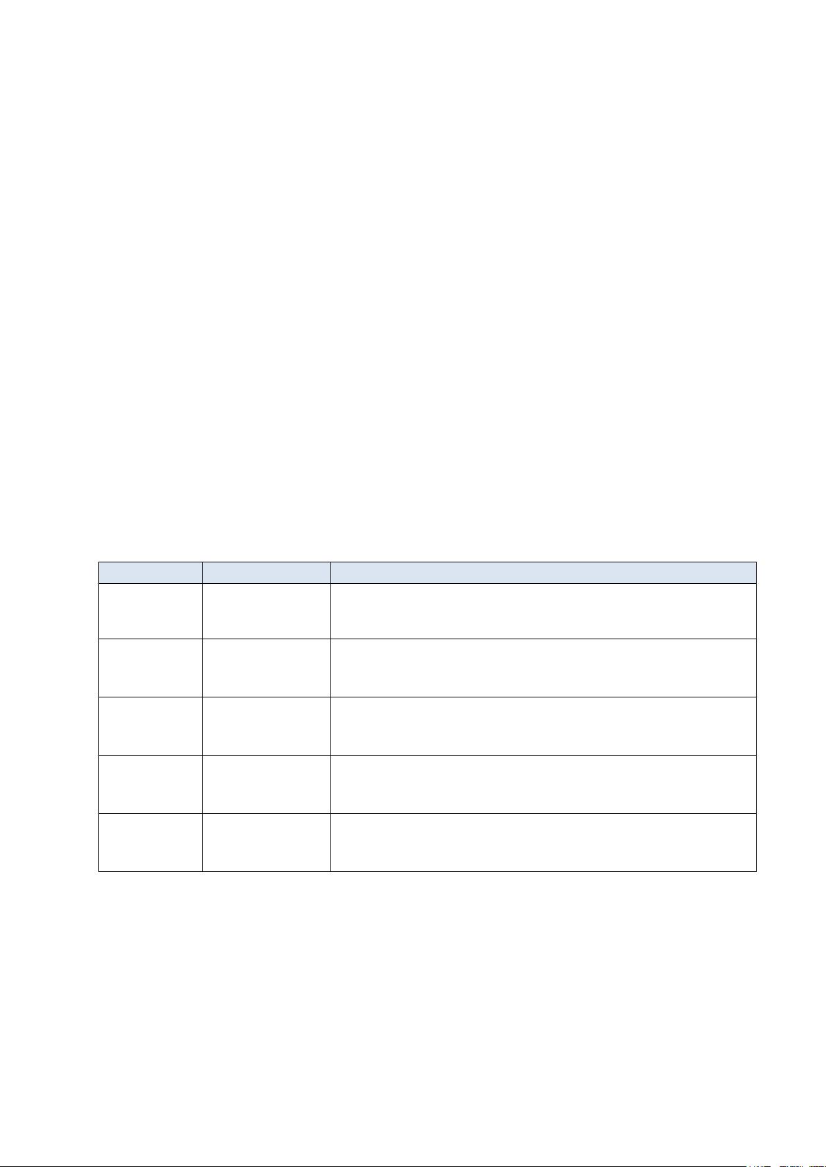
P50 Probe Handler
The ‘P50’ probe handler is designed to align the ultrasonic probe
on to straight pipes from 50mm in diameter up to flat surfaces.
The spring-loaded probe and V shaped block allow the probe to be
positioned correctly on a straight pipe and move to accommodate
different pipe diameters.
A gimbal allows the probe to move to align on to the straight pipe
surface when used with a ROV manipulator arm.
The probe handler can be fitted with a choice of manipulator
handles; T Bar or Fishtail.
Este manual sirve para los siguientes modelos
2
Tabla de contenidos
Otros manuales de Instrumento de medición de Cygnus


Manuales populares de Instrumento de medición de otras marcas


Endress+Hauser
Endress+Hauser Proline Promag 50 Especificaciones técnicas

Siemens
Siemens SITRANS F Coriolis FCT030 Manual de lista de piezas

KLINGER
KLINGER CMF V Series Manual de usuario

EXFO
EXFO FTB-2 Manual de operación y mantenimiento

Keysight
Keysight M8290A Manual de usuario

ADTEK
ADTEK MW-5 Manual de usuario