Cooper Security 4618 Manual de usuario

496371 Issue 1 1 of 20
4618/4619
Installation Guide
Compatible Equipment
All 4600 range transmitters
4594UK-00 1/4 wave whip aerial for indoor use
4595UK-00 Four element Yagi directional aerial for long range out-
door use.
4597UK-00 1/2 wave base loaded vertical aerial for outdoor use
4598UK-00 1/4 wave helical aerial for indoor use
4599UK-00 1/4 wave helical aerial with 90 degree bend for indoor use

2 of 20 496371 Issue 1
Introduction
The 46RX family of eight-channel receivers can be used either as stand
alone units, or the radio interface for a wired alarm panel.
The 46RX family comprises three variants:
• The 4618-50 which requires an external 12V power supply.
• The mains powered 4618-60.
• The 4619-50 expansion unit.
Each of the 46RX family provide three common outputs. By adding the
optional 8-Channel Relay Card 4618EUR-55 each variant can also provide
eight additional output channels.
By connecting up to three expansion units an installation can be made to
cover 32 separate, programmable channels.
The 46RX family works with the 4600 range of Scantronic transmitters.
Any one of a range of aerials can be fitted to the 4618-50/60 receivers.
Each member of the 46RX family provides space for a backup battery. A
suitable battery is a sealed 1.2 Ah 12V lead acid type.
Technical Specification
Dimensions h x w x d 170 x 260 x 75mm.
Electrical
Input supply 4618-60 225 - 253 VAC, 50 Hz, 30 VA max.
Power Supply Current
available4618-60: 400 mADC.
Input supply 4618-50 11 -14 VDC.
BatteryCapacity 12 V, 1.2 Ah (per unit).
PhysicalBatterysize 100 x 60 x 50 mm.
Float Charge Voltage 13.7V (4618-60 only).
Low Battery Threshold Voltage 10.5 V.
Battery charging time < 24 hrs.
Quiescent current rating 55 mA (4618-50/60 on 12V input).
75 mA (4618-60 on mains).
35 mA (4619-50).
Auxiliary power o/p: 1 A max, 250 mA continuous.
Sounder o/p: 250mA max at 12V.
Temperature -10° to +55° C, humidity up to 80% non-
condensing.
4618

496371 Issue 1 3 of 20
Protection
Mains Input Fuse: 1A.
Channel Relays
Current requirement: 15 mA (per active relay).
Max switching voltage: 24VDC.
Max switching current: 2A.
Radio
Frequency 173.225MHz.
Fully DTI approved - no license required.
BS6799 Class 3 with Jamming Detection switched ON.
BS6799 Class 2 with Jamming Detection switched OFF.
TECHNICAL DESCRIPTION
Physical Layout
The 46RX family are wall mounted units housed in a polycarbonate box
made to BS4734 requirements. Figure 1 shows the general layout of the
main components.
Figure 1. Internal Layout of 46RX Family
4618 Protection

4 of 20 496371 Issue 1
The receiver and decoder circuits are on the main circuit card mounted
securely within the lid. The body of the box contains space for:
• The power supply (fitted in the 4618-60 only)
• A backup battery (not supplied)
• The 4618EUR-55, an optional 8-channel relay output card.
There differences between the three variants of the 46RX are:
• The 4618-50 power supply enclosure is empty, and there is no mains
cable terminator.
• The 4618-60 is fitted with a mains power supply, and mains cable
terminator and fuse.
• The 4619-50 has no mains power supply, and no receiver on the main
circuit board.
Figure 2 is an expanded view of the main circuit card showing the location of
the connectors and controls.
Figure 2. Main Circuit Card Controls And Connectors
Technical Description 4618

496371 Issue 1 5 of 20
Inputs
Radio
The 4618-50 and 4618-60 contain a standard Scantronic radio receiver which
connects to a BNC aerial socket mounted on top of the case.
Each detector sends information to the receiver using an attached radio
transmitter. The transmitter relays the information in the form of radio data
packets, using an FM signal. The signal contains a code identifying the
transmitter and information on the state of the detector. Every receiver within
range picks up the transmitter’s information, but reacts only to those transmit-
ters it has been programmed to notice.
Mode Switches
The Mode Switches are the controls that tell the system which transmitters to
notice, and what to do with the information received. Figure 2 shows the
location of the Mode Switches on the main circuit card in the lid.
Tamper
The 46RX family contain an internally mounted tamper switch to detect
opening of the case lid (see Figure 2). The switch gives a normally closed
loop isolated from any circuits on the main circuit card. This output can be
used as required. The switch contact opens when the lid opens.
Jamming
The 46RX family can detect radio jamming if Mode Switch 3 is ON. The
cause of jamming may be interference from nearby equipment, or the re-
ceiver detecting the radio carrier continuously. See “Fault Finding” for more
information.
Reset
The 46RX family have a Reset button on the front control panel. Pressing
Reset clears all the output channels and LEDs.
If you have an expanded system with two or more members of the 46RX
family connected together, then:
• Pressing Reset on the 4618-50/60 will reset only the 4618-50/60, and
not any attached 4619-50s.
• Pressing Reset on an attached 4619-50 will reset that unit, but not any
of the other units connected to it.
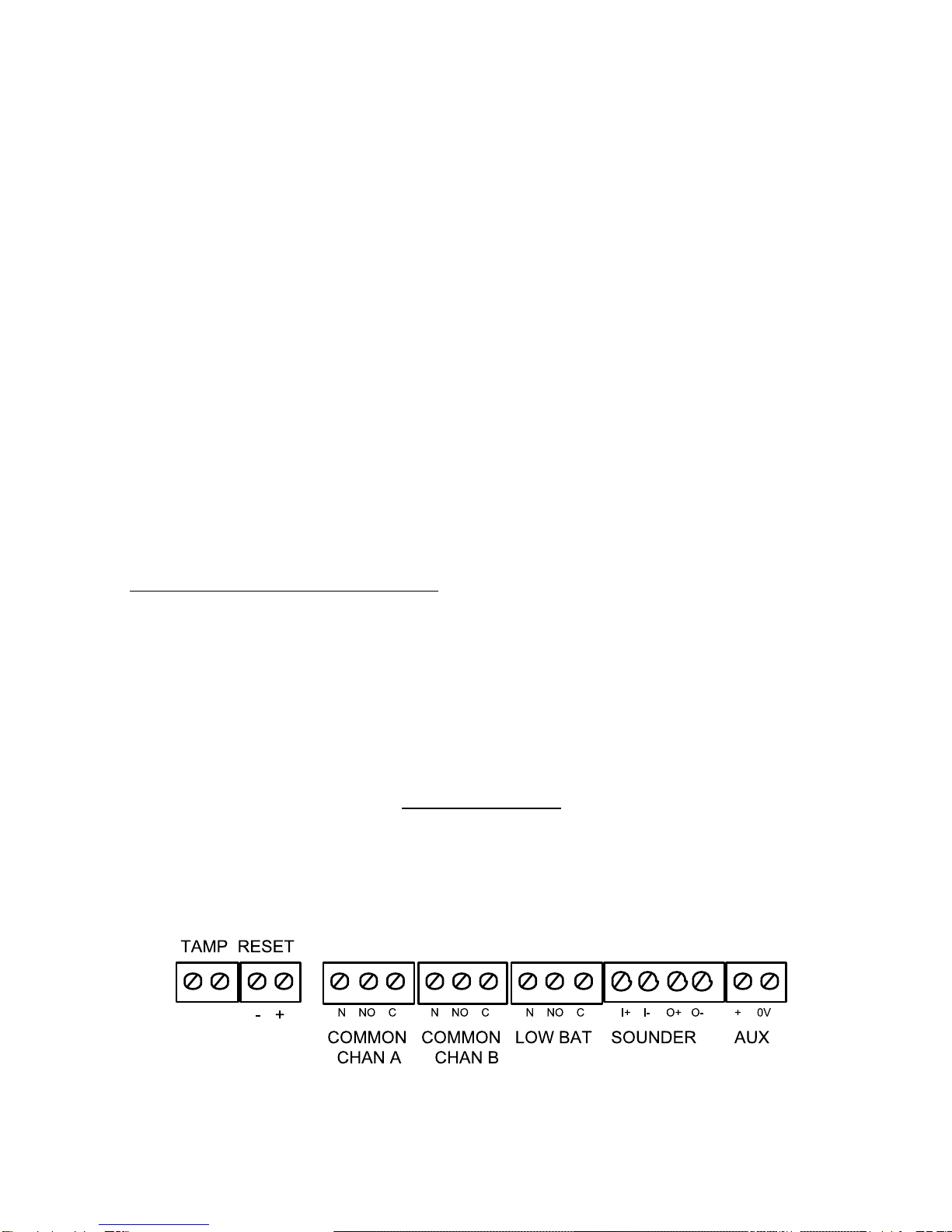
Each member of the 46RX family also has a connector for an external reset
signal (see Figure 2). By applying 12VDC to the positive terminal of the reset
connector and then removing it you can reset a system of connected 46RX
family units.
4618 Inputs

6 of 20 496371 Issue 1
Outputs
Front Panel
Each member of the 46RX family uses the display panel shown in Figure 3.
Figure 3. 46RX Family Display Panel
The vertical column of eight LEDs indicates the status of each channel
output.
The symbols on the right of the panel have the following meanings:
Power
Transmitter Low Battery
Jamming
A Common Output A
B Common Output B
Reset
Common Output Relays
Members of the 46RX family provide three output relays: Common Output
Channel A, Common Output Channel B and Low Transmitter Battery. Figure
2 shows their position and connectors.
The Normally Open, Normally Closed and Common Terminals of the relays
provide voltage free change over contacts.
The 46RX family use the Common Output Channel relays (and LEDs) to
report the status of transmitters. See Programming for more information.
The 46RX family use the Low Transmitter Battery relay to report that a
transmitter's battery is failing. See “Fault Finding” for more information.
Outputs 4618

496371 Issue 1 7 of 20
Optional 8-Channel Relay Card
Each member of the 46RX family also provides eight channel outputs for
signalling the state of associated transmitters. The channel outputs can drive
a bank of eight relays, mounted on a separate circuit card in the body of the
case. Each relay provides normally open, normally closed, and common
terminals.
The relay card, part number 4618EUR-55, is optional and must be purchased
separately.
Internal Sounder
The main circuit card in the lid carries a piezo electric sounder. Its terminals
are isolated from the other circuits on the card, and are available at a con-
nector at the bottom of the card. (See Figure 2.)
Next to the sounder terminals are the sounder output terminals. These can
be used to drive the internal sounder or an external sounder. The sounder
output comes on every time Common Output A or B comes on. See “Unit
Connection” for details of connecting the sounder output to the internal
sounder.
Expansion Units (4619-50)
If you want to receive more than eight channels from transmitters, you can
use 4619-50s as expansion units. The 4619-50 is physically similar to a
4618-50, except that it does not possess a radio receiver.
Once connected, each 4619-50 behaves like an independent unit, and can
be programmed separately from all the other units in the installation. You
should make sure that each unit has its own site code.
Connection
You may connect each member of the 46RX family to a control panel either
from the connectors on the main circuit card, or from the output connectors
on the eight-channel relay card
Figure 4 shows in detail the connectors available on the main circuit card.
Figure 4. Alarm Panel Connectors On Main Circuit Card.
4618 Optional 8-Channel Relay Card

8 of 20 496371 Issue 1
External Reset Connection
Figure 5. External Reset Connection.
When the user starts the control panel exit timer the Detector Reset output
removes the positive feed for six seconds. This clears the latched channels.
Connecting the Sounder
Figure 6. Sounder Connection.
Connecting the Optional 8-Channel Relay Card
Figure 7 shows the connectors available on the optional 8-channel relay card.
Figure 7. Optional 8-Channel Relay Card Connectors.
External Reset Connection 4618

496371 Issue 1 9 of 20
Expansion Units
Installation
4619-50 expansion units are supplied with an 80 cm cable to connect them to
a 4618-50 or 4618-60. Ensure that you position expansion units close
enough to the 4618-50 or 4618-60 so that the cable can connect them both.
NOTE: Do not attempt to modify the cable supplied, or use a substitute.
Connection
The recommended method of connecting 4618-50/60 and 4619 is to "daisy-
chain" them together, as shown in Figure 8.
4618-50 4619-50 4619-50
Figure 8. Connecting Expansion Units.
You can connect the units in any order. Use Exp 1, Exp 2, or both connectors
in any unit.
PROGRAMMING
Initial Start Up
Before applying power to the system make sure all expansion units are
installed and connected.
For Systems Using a 4618-60:
NOTE: When installing the equipment for the first time at a new site, for a 4618-60
connect the mains power first and then the battery. At subsequent mainte-
nance, or re-installations at existing sites, connect the battery first and then the
supply. The instructions below assume that you are installing the equipment at
a new site.
1. For ALL units in the system set Mode Switch 2 (Power Mode) ON:
on
1 2 3 4 5 6 7 8
2. Make sure the power lead from the transformer is plugged into the 4618
AC Power Input connector on the circuit card.
3. Wire in the mains power supply from a non-switched, fused (1A rating),
spur point.
4618 Expansion Units

10 of 20 496371 Issue 1
You should see the Power LED glow. If the sounder is connected you
should hear a short tone.
For Systems Containing a 4618-50
1. For ALL units in the system set Mode Switch 2 (Power Mode)
to OFF:
on
1 2 3 4 5 6 7 8
2. Connect the external 12V supply.
You should see the Power LED glow. If the sounder is connected you
should hear a short tone.
To Connect a Backup Battery
1. Connect the battery lead spade connectors to the battery terminals
(observingpolarity)
2. Connect battery lead connector to the Batt. In/Out connector on the
main circuit card.
Note: If the sounder gives a continuous tone when you apply power then the mode
switches are set to an unacceptable mode number. The 8-channel LEDs will
also show a running pattern of flashes. Set the Mode Switches to the required
mode for your application.
Setting Up Receiver And Transmitters
To make the 46RX family operate correctly you must set two groups of
switches:
1. The site code switch on both the transmitters and the 46RX family
receiver to the same pattern.
2. The mode switch on the 46RX family receiver to the correct mode.
Figure 4 shows the switches in more detail.
Figure 9. Site Switch and Mode Switch
Setting Up Receivers and Transmitters 4618
Este manual sirve para los siguientes modelos
1
Tabla de contenidos
Otros manuales de Receptor de Cooper Security


