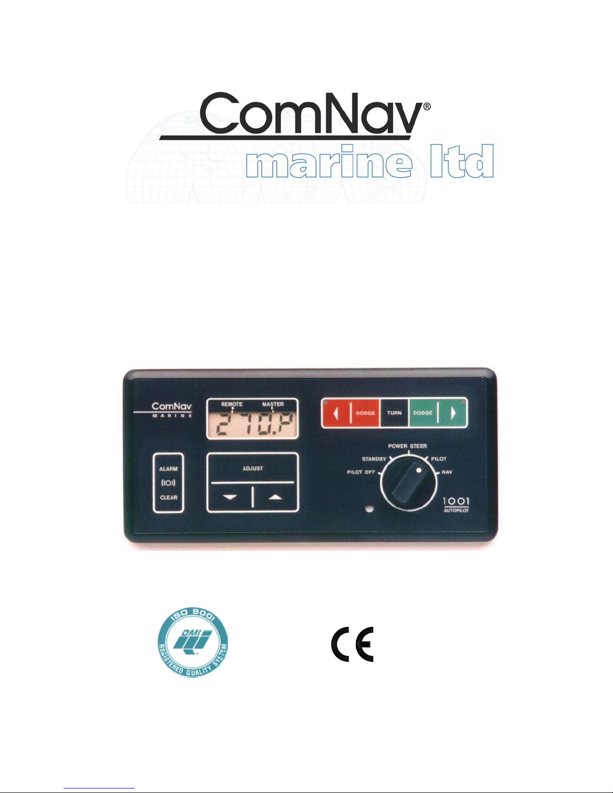
ComNav 1001 Manual de usuario

Installation & Operation Manual
ComNav 1001 Autopilot
COMPLIES WITH
CE REGULATIONS
P/N 29010007


WARRANTY NOTICE
Prior to the installation and/or operation of the Equipment, ensure
that you read, understand and accept the conditions of the warranties
as detailed on the following pages.
OPERATORS WARNING
This Autopilot will automatically steer your vessel however, it
is only an aid to navigation. Its performance can be affected
by many factors including equipment failure, environmental
conditions and improper handling or use. This system does
not reduce your responsibility for the control of the vessel
when underway. You must always be in a position to monitor
the course, supervise the Autopilot, and resume manual
control if the need to do so arises.
Whenever underway, your vessel must be under the control of
a qualified and alert person.

1
TABLE OF CONTENTS
1001 AUTOPILOT SYSTEM DRAWING _________________________________________ 3
BASIC OPERATION __________________________________________________________ 3
AUTOPILOT _____________________________________________________________________ 4
REMOTE CONTROL _____________________________________________________________ 6
INTRODUCTION ____________________________________________________________ 7
SPECIFICATIONS ___________________________________________________________ 8
1001 AUTOPILOT INTERCONNECTION DIAGRAM ______________________________ 9
OPTIONAL DRIVE SYSTEMS ________________________________________________ 11
INSTALLATION INSTRUCTIONS_____________________________________________ 12
AUTOPILOT____________________________________________________________________ 12
COMPASS______________________________________________________________________ 13
DISTRIBUTION BOX ____________________________________________________________ 18
RUDDER FOLLOWER___________________________________________________________ 21
NAVIGATION INTERFACE __________________________________________________ 24
CROSS TRACK ERROR RESPONSE ______________________________________________ 26
CHECKSUM EVALUATION______________________________________________________ 27
DOCKSIDE SET-UP _________________________________________________________ 28
SETTING OF RUDDER TRAVEL LIMITS __________________________________________ 28
ADJUST RUDDER ANGLE INDICATOR (if installed) ________________________________ 29
CONFIGURING THE COMPASS __________________________________________________ 30
NAVIGATION EQUIPMENT INTERFACING _______________________________________ 30
SEA TRIALS________________________________________________________________ 31
CONTROLS ________________________________________________________________ 36
MASTER SELECT SWITCH ______________________________________________________ 36
MEMBRANE KEYPAD___________________________________________________________ 37
SPECIAL TURNS____________________________________________________________ 40
EMERGENCY TURN ____________________________________________________________ 40
CONTINUOUS TURN____________________________________________________________ 40
U TURN ________________________________________________________________________ 41
OPERATION _______________________________________________________________ 42
STANDBY ______________________________________________________________________ 42
POWER STEER _________________________________________________________________ 43

2
PILOT _________________________________________________________________________ 44
NAV ___________________________________________________________________________ 47
REMOTE CONTROLS ___________________________________________________________ 48
REMOTE CONTROLS _______________________________________________________ 50
COMNAV 101 REMOTE CONTROL _______________________________________________ 50
COMNAV 201 REMOTE CONTROL _______________________________________________ 53
COMNAV 211 REMOTE CONTROL _______________________________________________ 54
ERROR CHECKING _________________________________________________________ 55
PROBLEM SOLVING ____________________________________________________________ 59
CE COMPLIANCE __________________________________________________________ 62

3
1001 AUTOPILOT SYSTEM DRAWING

4
BASIC OPERATION
AUTOPILOT
1. TO INITIALIZE THE AUTOPILOT\
STANDBY MODE
zTurn the master select switch to
the STANDBY position. The display will
show the vessel's current compass
heading. If the heading displayed by the
autopilot does not agree with the
compass, press the ADJUST key twice to
display the current heading offset, and
then use the up or down ARROW key to
adjust the offset by the amount of the
error.
zTo turn on the speed sensitivity
that switches between FAST and SLOW
when in PILOT or NAV, with the Pilot in
Standby press the ADJUST key until
'SP: 0' is displayed. Press the up
ARROW key until the desired speed is
displayed.
zTo turn off the speed sensitivity,
press the down ARROW key until the
display reads 'SP: 0'.
zIf the display is too bright or too
dim when viewed in full darkness, press
the ADJUST key until 'Lt ' is displayed,
and then use the up or down ARROW
key to adjust the minimum brightness
level between 0-9.
zTo select a Special Turn as
described in (4) below, press the TURN
key followed by either the red or green
ARROW key.
zTo initiate a Full Reset, press and
hold both the up and down ARROW keys
for one second. This will reset all autopilot
parameters back to factory settings and
the Pilot will go into Reset mode. A
dockside set-up will be required after
every Full Reset.
2. TO POWER STEER THE VESSEL\
POWER STEER MODE
zTo turn the rudder to port and to
starboard, turn the master select switch to
the POWER STEER position. While
either the red or green ARROW key is
pressed, the display will show the
vessel’s rudder angle and will show the
vessel's current compass heading at all
other times.
zTo display the vessel's rudder
angle, press the TURN key once. To
return compass information to the display,
press the TURN key again.
zTo zero the digital rudder angle
display, turn the rudder to dead ahead,
press the ADJUST key until the flashing
rudder angle display appears and press
the up or down ARROW key until the
rudder angle display shows ' :00'.
3. TO BEGIN AUTOPILOT CONTROL
OF THE VESSEL:
zTo have the vessel continue on its
present heading under autopilot control,
turn the master select switch to the
PILOT position.
zTo select either the 'FASt' (High
Speed) mode or the 'Slow' (Low Speed)
mode, press the ADJUST key once
followed by the up or down ARROW key.
This will be done automatically if the
speed sensitive switching has been
turned on in (1) above.
zTo adjust the rudder gain setting
for the High or Low speed mode, press
the ADJUST key until 'rud' is displayed,
followed by the up or down ARROW
keys. Similarly adjust the counter rudder
('ctr') and yaw ('YAW') settings for best
steering.

5
4. TO CHANGE THE VESSEL'S
COURSE:
zTo obtain the desired course,
leave the master select switch in the
PILOT position. Estimate the number of
degrees of course change required.
zUntil the display shows the desired
course, alter the course in one degree
steps by pressing and releasing either the
red or green ARROW key.
--- Or ---
Alter course by ten degrees per second
by pressing and holding either the red or
green ARROW key.
zTo select a special turn (U-turn,
Emergency Turn, or Continuous Turn),
with the Pilot in Standby mode, press the
Turn key once followed by the Green key
until the desired Turn is displayed.
zTo adjust the rate at which the
vessel will turn to the new course, press
the ADJUST key until 'trn' is displayed
and then press the up or down ARROW
key
5. TO DODGE THE VESSEL OFF
COURSE\PILOT MODE
zTo avoid obstacles in the water,
press either the red or green DODGE key
for a panic turn in the desired direction.
zTo keep the vessel off course,
after it has turned far enough to clear the
obstacle, press and hold both DODGE
keys.
zTo return to the programmed
course at the rate set by the turn rate
control. Release the DODGE key
6. TO INTERFACE WITH A
NAVIGATION COMPUTER\NAV MODE
zStart navigating towards a
selected route or waypoint, using a
Navigation Computer which has an
NMEA 0183 output.
zTurn the autopilot master select
switch to the NAV position. The autopilot
will set its own course using information
sent to it by the Navigation Computer.
zTo select the response to cross
track error (normal or reversed), press the
TURN key and then the green ARROW
key.
zThe DODGE keys operate as
described in (5) above, except that the
vessel will return to the original track to
the waypoint, rather than the original
course, when the DODGE keys are
released.
For more complete operating instructions,
refer to the CONTROLS and
OPERATION sections.

6
REMOTE CONTROL
The autopilot master control unit must be on to use any remote control. The
vessel’s compass heading is shown at all times on the display of the unit that is
NOT in control. As a further reminder, the function indicator (see Figure 8) will be
flashing on the display of the unit that is NOT in control.
1. TO USE THE COMNAV 101
REMOTE CONTROL:
zTo take control at the Remote,
press both its pushbuttons for one
second. The command point on all
displays will move to the REMOTE
position. This control operates identically
to the autopilot, except that there is a
toggle switch, used together with one of
the pushbuttons, to dodge or to initiate a
special turn.
zTo recall the vessels last course,
hold the toggle switch in the DODGE
position while turning the master select
switch from POWER STEER to PILOT.
The course that the autopilot was steering
when it was last in PILOT will be recalled.
(If the autopilot has not been in PILOT
since it was turned on, the course the
vessel was on at the moment the
autopilot was turned on will be recalled.)
2. TO USE THE COMNAV 1101
SECOND STATION:
zTo take control at the Second
Station, press both DODGE keys for one
second. The Command Point on all
displays will move to the REMOTE
position.
zThe 1101 second station operates
identically to the autopilot, except that the
OFF/FUNCTION will not operate. The
autopilot must be turned ON and OFF
from the autopilot front panel.
3. TO TAKE CONTROL AT THE
AUTOPILOT FRONT PANEL:
zTo take control at the autopilot
front panel, press both the red and green
ARROW keys on the autopilot front panel
for one second. The command point on
all displays will move back to the
MASTER position.
For more complete operating
instructions refer to the REMOTE
CONTROLS section.
WARNING
If the unit that will take control is
not in the same mode as the unit
currently in control, a sudden
course change could occur.

7
INTRODUCTION
This autopilot is a microprocessor
operated PID (Proportional-Integral-
Differential) controller, working from either
a high quality, externally gimballed
magnetic ships steering compass fitted
with a fluxgate sensor or a direct earth’s
field sensing fluxgate compass.
Heading information is compared against
the programmed heading, and the
desired rudder position determined. The
desired rudder position is compared
against the actual rudder position
transmitted by the rudder follower. If they
are not the same, either the Port or
Starboard output line is activated.
The Port and Starboard output lines are
active low (i.e. switch to ground), and can
drive a load of up to 3 amps. They are
designed to operate solenoid valves in a
hydraulic steering system.
A speed control signal is also available for
use with variable speed rudder drives.
The outputs, either by themselves or with
an optional solid state drive box, can be
adapted to operate a wide variety of
power steering systems.
If the autopilot is installed as a retrofit, it is
usually possible to use the existing power
steering installation. The autopilot can
operate from either 12 or 24 VDC power
systems.
The autopilot has our unique Ghost
Rudder feature. In case of a rudder
follower failure the autopilot will
automatically switch to Ghost Rudder,
which calculates the rudder position
instead of measuring it, and continue to
operate at a reduced performance level.
The autopilot is equipped to interface with
a GPS, Loran C, or any other navigation
computer which outputs one of the NMEA
0183 formats at 4800 Baud.
The autopilot is designed to accept one
remote control.
By adding the optional REMOTE
EXPANDER, the autopilot can support
any combination of up to four remote
controls or second stations.
Figure 1 shows the possible
interconnections between the autopilot,
it’s accessories, and external equipment.
Tabla de contenidos
Otros manuales de Sistema de piloto automático de ComNav


