Comelit ILS-2 Manual de usuario

1
ASPIRATING SMOKE DETECTOR, 1 ZONE, 2
DETECTORS
ILS-2

2
DISCLAIMER
The content of this document is provided “as seen”. No responsibility is taken and no guarantee (express or
implied) is made in terms of the complete nature, accuracy or reliability of the content of this document. The
manufacturer reserves the right to make changes to the design or the specifications, without any obligation and
without prior notice. Unless otherwise stated, any express or implied guarantee is strictly excluded; this includes,
without restrictions, all implied warranties relating to saleability and fitness for particular purposes.
Conventions used
The following typographic conventions are used in this manual:
Convention
Description
Bold
Used to indicate: emphasis used for menu names, menu options,
toolbar icons
Italic
Used to indicate:
links to other sections
of this manual or other documents, or to indicate the result of
an action.
The following symbols are used in this document:
Convention Description
Caution: this symbol is used to indicate danger to the equipment. The danger
may include loss of data, physical damage or permanent corruption of
configuration parameters.
Danger: this symbol is used to indicate a risk of electric shocks, which
could result in death or permanent injury.
Danger: this symbol is used to indicate a danger of inhaling dangerous
substances, which could result in death or permanent injury.

3
Summary
1 Introduction ............................................................................................................................................................. 4
2 Installing the detector .............................................................................................................................................. 4
3 Terminal block connections ..................................................................................................................................... 4
3.1 Connection to external devices ......................................................................................................................... 5
4 Installing the piping .................................................................................................................................................. 7
4.1 Piping specifications .......................................................................................................................................... 7
4.2 Fixing ................................................................................................................................................................. 7
4.3 Bends ................................................................................................................................................................. 7
4.4 End caps ............................................................................................................................................................ 8
4.5 Sampling holes .................................................................................................................................................. 8
4.6 Air outlet ........................................................................................................................................................... 8
4.7 Filters ................................................................................................................................................................. 8
4.8 Standard pipe configurations ............................................................................................................................ 9
5 Detectors .................................................................................................................................................................. 9
6.2 User functions ................................................................................................................................................. 11
6.3 Setup notes ..................................................................................................................................................... 14
7 Testing .................................................................................................................................................................... 16
7.1 Point detectors ................................................................................................................................................ 16
7.2 System ............................................................................................................................................................. 16
8 Maintenance .......................................................................................................................................................... 17
9 EN54-20 Sensitivity classes .................................................................................................................................... 18
10 Troubleshooting ................................................................................................................................................... 19
11 Specifications ....................................................................................................................................................... 20

4
1 Introduction
The ILS-2 System is an aspirating detector which uses a network of sampling pipes to channel air to the two high-
sensitivity point detectors housed inside the casing of the main detector. The use of a network of pipes offers a
larger area of protection coverage in comparison to traditional point detectors.
Up to three alarm levels can be configured, depending on the specific application.
A high-efficiency aspirator and a system of flow sensors guarantee correct airflow.
The amount of extracted air can be displayed on a 10-LED bar graph which also indicates the low and high airflow
thresholds.
Parameter configuration can take place entirely using the integrated buttons on the sensor.
ILS-2 is an autonomous device capable of signalling fault and alarm events via a relay with voltage-free contacts.
These contacts may then be connected to a monitoring and signalling control panel.
Important note: Aspirating Fire Detection Systems installed in the EU since June 2009 must comply with the
Construction Products Regulation Directive (89/106/EEC) and the corresponding European standard EN54-20.
This appliance has been tested and approved to guarantee general compliance with the abovementioned directive
and standards, strict adherence to this Product Guide is required to ensure that the installation meets all aspects
of these requirements.
2 Installing the detector
Note: this device should be installed by authorised personnel in accordance with local and national regulations.
Remove the transparent cover using the keys provided and loosen the fasteners. Use the template to position
the fixing holes accurately and secure the unit to a surface (wall or ceiling) using the 4 corner fixing points.
Make sure the wall plugs and fixing screws are suited to the installation surface.
3 Terminal block connections
For the system to work properly, it is essential that the enclosure is sealed so that air can only be drawn into the
system from the sampling pipe(s). For this reason, all wiring must pass through the specific cable routes and no
other holes must be made. To run the cable through the relevant inlet, make a small hole (using the tip of a
screwdriver) in the middle of the membrane and push the cable through into the unit. The hole in the membrane
can accommodate cables with a diameter between 4 and 10 mm, thus guaranteeing an airtight seal.
To access the terminal block and connect the cables, it is necessary to remove the display plate housing the
indicators, which is held in place and shut off by the transparent top cover. Take care when removing the board
and make sure that the ribbon cable underneath is not stretched. The ribbon cable must be removed from the
connector on the underside of the board to allow full removal of the board (see figure 2 and 3).
To prevent electric shocks or potential damage caused by fan rotation, cut off the
power supply before removing the cover.
All connections from the site to the main circuit board are made via terminals that can accommodate cables up to
2.5 mm2.

5
3.1 Connection to external devices
Figure 3-1: terminal block for connection to external devices
3.1.1 Connecting the Batteries / Power supply input
Figure 3-2: Ferrite core
ILS-2 must be powered by means of a 24 Vdc power supply unit with EN54-4 approval. The power supply must
be connected using the BATTERY terminals on board the terminal block, observing the correct polarity. The
minimum recommended size is 16 x 0.25 mm (18 AWG), or greater if the power supply unit is further than 5 m
away from the sensor.
A ferrite core is supplied to ensure correct electromagnetic compatibility (EMC). This core must be positioned
inside the unit and the power supply cables wound as shown in figure 3-2. The type of power supply unit required
depends on the speed of the fan used for the application; please refer to Table 11-2: Current Consumption vs Fan
Speed.
3.1.2 ACTION 2, ACTION 1 - Relay output
The voltage-free contacts of the relay ACTION (ACTION) will change status when the pre-alarm level is
exceeded. The Normally Open (NO) and Normally Closed (NC) contacts on the terminal block are available.
3.1.3 FIRE 2, FIRE 1 - Relay output
The voltage-free contacts of the relay FIRE (FIRE ALARM) will change status when the alarm level is
exceeded. The Normally Open (NO) and Normally Closed (NC) contacts on the terminal block are available.
3.1.4 FAULT 2, FAULT 1 - Relay output
In fault conditions, the FAULT relay will change status. The Normally Open (NO) and Normally Closed (NC)
contacts on the terminal block are available.
Note: NO/NC shown in the terminal block refers to the un-powered sensor status. In normal operating
conditions (power supply present) the NO contact is closed, while the NC contact is open.

6
3.1.5 External Reset
The application of a voltage of +24 Vdc to these terminals triggers a reset of all fault and alarm events
present.

7
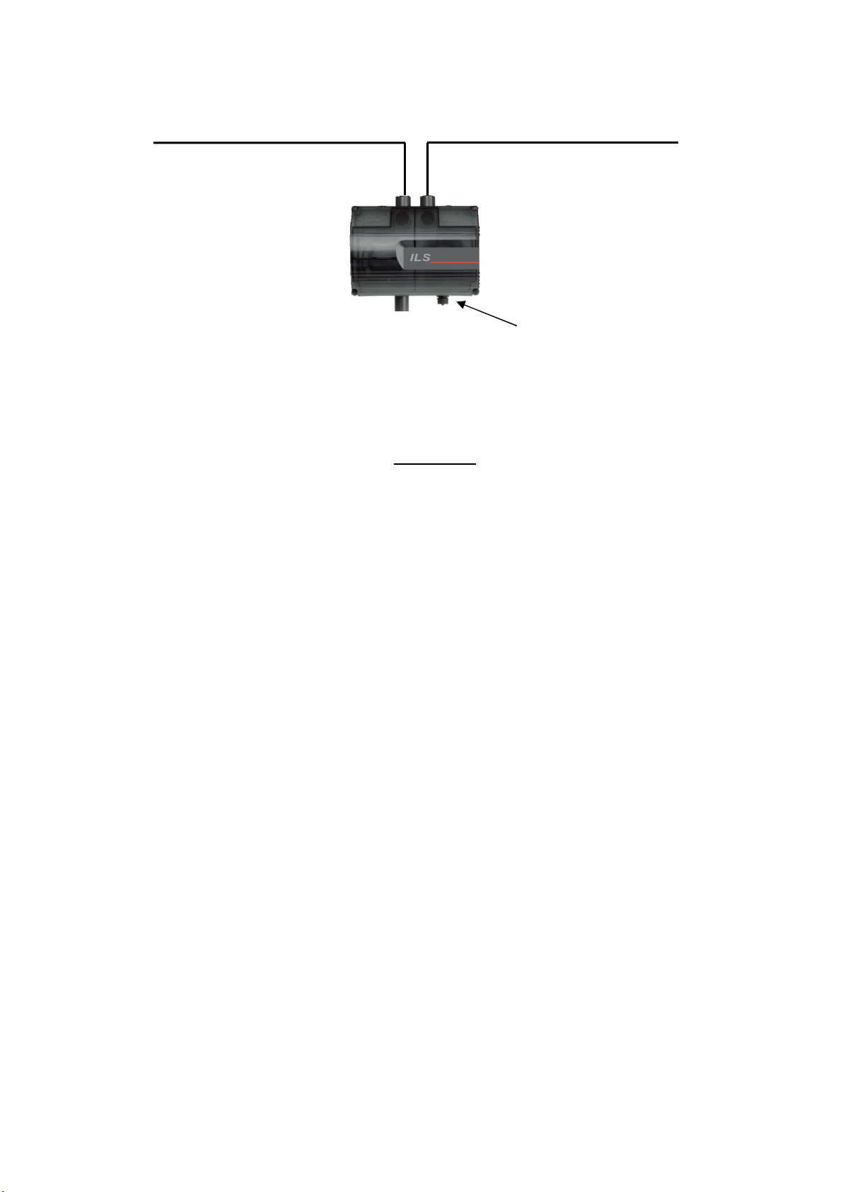
3.1.6 USB Connector
The detector is equipped with a USB type B connector to allow connection to a PC via a US cable (not supplied).
This communication port allows configuration of the sensor, and downloading of logged data using the VSC
software.
The connector is protected by a screw-fit cover and this must be re-fastened after every use, to prevent dust and
dirt from settling on it.
4 Installing the piping
Several standard configurations of the pipe network are illustrated below.
TThe sizing software ASPIRE2 must be used to calculate the channelling time, dilution effects etc. for all the
pipe networks required for individual applications.
Use 25 mm red ABS piping with sampling holes drilled along its length. The piping will terminate with an end
cap, with a hole drilled in its centre. The position of each sampling hole should adhere to guidelines for point
smoke detectors. It is important to note that the concentration of smoke entering a single hole will be diluted
by clean air from other sampling holes and from the end cap hole.
4.1 Piping specifications
In accordance with EN54-20 standards, the pipes must be red ABS and conform to EN 50086-1
(Crushing 1, Impact 1, Temperature 31) with a nominal external diameter of 25 mm. The pipes are
normally supplied in 3-metre lengths and cut as required, but linked using solvent welded sockets or
connected with socket unions (inspectable).
IMPORTANT note: the ILS-2 pipe inlets are tapered so as to allow “push-fit” coupling of the piping coming
from the site. The end of the inlet pipe must be cut cleanly so as to allow airtight
coupling with the tapered inlet. The inlet piping junction with the tapered collector
MUST NOT BE GLUED: doing so will invalidate the sensor warranty.
4.2 Fixing
The standard fixing method for piping requires special clips or clamps. The fixing spacing (distance between two
adjacent clips) is typically 1.5 m.
4.3 Bends
Figure 4-1: 45° bend and 90° bend
The available bends are 90° and 45°. It is important to use 90° swept bends and not “sharp” ones, as sharp
bends introduce high pressure losses and increase the channelling time for the sampling holes downstream of
the bend.

8
4.4 End caps
Figure 4-2: End cap with central hole
The sampling pipes terminate with a cap which has a hole at the centre. The end cap hole should be considered
as the final sampling hole.
4.5 Sampling holes
The sampling holes are distributed along the piping and are usually drilled once the pipes have been installed,
using a drill bit with a suitable diameter. Drilling can be carried out prior to installation, taking care to space the
holes correctly in the area you wish to protect. Drilling should also be performed in such a way that residual ABS
is not left around the hole. After drilling, remove any ABS residue that has collected inside the pipe. This can be
done by sucking the air out with an external extractor, or by blowing compressed air through, which will push the
debris through to the end of the pipe; in the latter case you will need to fit the end cap afterwards. In standard
applications, the sampling hole faces “downwards”.
4.6 Air outlet
The extracted air, after being analysed, exits via the relevant hole on the enclosure. In some applications, the air
outlet must be moved so that it is a certain distance from the detector; this requires an outlet pipe. This is
necessary when, for example, you wish to reduce the noise level, reduce the risk of outlet obstruction, or the static
pressure of the room in which the air is released must be the same as the room from which the air is extracted,
etc.
The maximum permitted length for this outlet pipe is 10 m, in order to minimise airflow reduction.
The air outlet must be positioned with care, to ensure it is not obstructed accidentally.
4.7 Filters
Figure 4-3: Filters at the inlet of the ILS-2 detector
The sampled air is passed through a filter (code: 02-FL53) before it enters the optical detection
chamber.
9
4.8 Standard pipe configurations
Figure 4-4: Standard configuration for ILS-2
The double pipe configuration can have a maximum length of 200 m (max. 100 m per incoming pipe), with up to
18 x 3 mm sampling holes and a 6 mm end cap hole for each pipe.
The pipes must be the same length and have the same number of holes.
All configurations with maximum permitted pipe length and/or maximum number of sampling holes should have
the Alarm (FIRE) threshold set to LEVEL 1 (maximum sensitivity) and the fan speed set to 9 (maximum). The
use of bends as described in section 4.3 will have a minimal effect on performance (e.g. response time).
Note: the abovementioned values are based on EN54-20 certification testing. A reduction in pipe length may be
reflected in a lower fan speed, just as fewer holes may be reflected in an increased sensitivity level.
Complex piping configurations must be checked using the ASPIRE2 software.
5 Detectors
Caution:
If the detector/s is/are removed for maintenance purposes, it/they must be fitted in the positions
described above.
Changing the position of the detector(s) may result in false reporting in the event of a fault or
alarm.
USB port Type “B”

10
6 Setup
6.1 Display functions
ALERT (Alert)
ACTION (Pre-alarm)
LED BAR CHART (Smoke level and Fan speed)
FIRE (Fire alarm)
SMOKE DETECTOR FAULT (detector fault -
1 per detector)
ISOLATE (Disabled=relays not active)
AIRFLOW OK - HIGH AIRFLOW - LOW AIRFLOW
POWER ON (Power supply present)
FAN FAULT (Fan fault)
GENERAL FAULT (General fault)
RESET
MAINS FAILURE (Mains pow. supp. fault)
UNLOCK (Unlocked)
BATTERY LOW (Battery low)
CODE ENTRY (Access code)
DETECTION MODE
Tabla de contenidos
Otros manuales de Detector de humo de Comelit


Manuales populares de Detector de humo de otras marcas


System Sensor
System Sensor DH500ACDC Manual de usuario

Resolution Products
Resolution Products RE612 CryptiX Manual de usuario

First Alert
First Alert PC900V Manual de usuario

Eminent
Eminent EM6590 E-Domotica Manual de usuario

Ei Electronics
Ei Electronics Ei Ei168RC Manual de usuario

Carrier
Carrier Kidde Quell Q301 Manual de usuario


