Centrix W20 Manual de usuario

HDVS IP CAMERA
W20 & W50
User Manual

Table of Contents
1. Overview ................................................................................................................................. 3
1.1 Features ....................................................................................................................... 3
1.2 Package Contents....................................................................................................... 4
1.3 Dimensions .................................................................................................................. 5
1.4 Connectors................................................................................................................... 6
2. Camera Cabling..................................................................................................................... 8
2.1 Connect Power ............................................................................................................ 8
2.2 Connect Ethernet Cable ............................................................................................. 8
2.3 Connect Alarm I/O....................................................................................................... 8
3. Installation.............................................................................................................................. 9
3.1 Ceiling / Wall Mounting............................................................................................... 9
3.2 Lens Adjustment (Vari-focal Lens only).................................................................. 10
4. System Requirements ....................................................................................................... 11
5. Access Camera ................................................................................................................... 12
6. Setup Video Resolution..................................................................................................... 16
7. Conguration Files Export / Import................................................................................ 17
Appendix A: Technical Specications......................................................................................... 18
Appendix B: Delete the Existing DC Viewer ............................................................................... 22
Appendix C: Setup Internet Security........................................................................................... 23
Appendix D: Video Resolution..................................................................................................... 24
2M- Quad Streams .................................................................................................................. 24
2M- Triple Streams .................................................................................................................. 28
2M- Dual Streams.................................................................................................................... 30
2M- Single Stream................................................................................................................... 30
2M Real time / 3M / 5M- Quad Streams.................................................................................. 31
2M Real time / 3M / 5M- Triple Streams.................................................................................. 36
2M Real time / 3M / 5M- Dual Streams ................................................................................... 39
2M Real time / 3M / 5M- Single Streams................................................................................. 40

3
1. Overview
Supported with both H.264 and MJPEG standard, the product series not only features
in superior Full HD resolution for real-time streaming at 25/30 fps, but also supplies D1
real-time streaming. With more computing power, the IP Camera could provide more
exibility for users and system managers.
1.1 Features
Progressive Scan CMOS Sensor
Quad Streams support
Dual Streams, Full HD 1080P real-time + D1 real-time
Quad Streams Compression:
H.264 Baseline / Main / High Prole + MJPEG
Multi-language support
Tampering Alarm
Wide Dynamic Range
Remote Zoom & Focus (Motorized Lens)*
Motion Detection
Privacy Masks
Smart Picture Quality / 3D Noise Reduction
Vertical View Mode (Image rotation by 90 derees)
Smart IR Mode
Network Failure Detection
Day/Night (ICR)
IR LED Module (working distance up to 25m)
Micro SD support
Weatherproof (IP66 International)
Sunshield*
Integrated Mounting Bracket with Cable Management
ONVIF Support
4
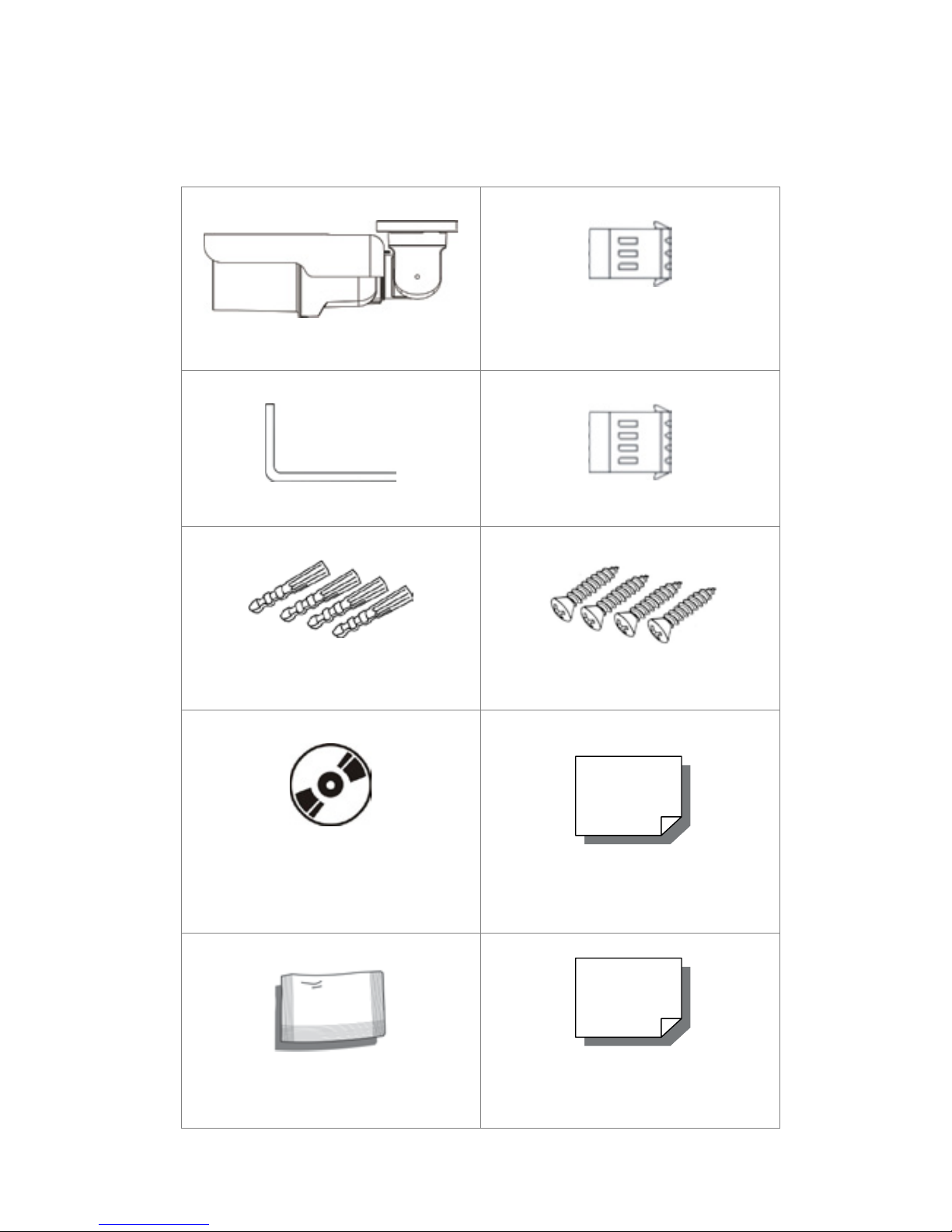
1.2 Package Contents
Please check the package contains the following items listed below.
IR Bullet IP Camera (Cable included) Power Terminal Block (x1)
M4 Inner Hex Wrench (x1) Alarm Terminal Block (x1)
Plastic Screw Anchors (×5)
M4 Self Tapping Screws (×5)
CD
(bundled software and documentation) Quick Guide
Desiccant Desiccant User Guide
5
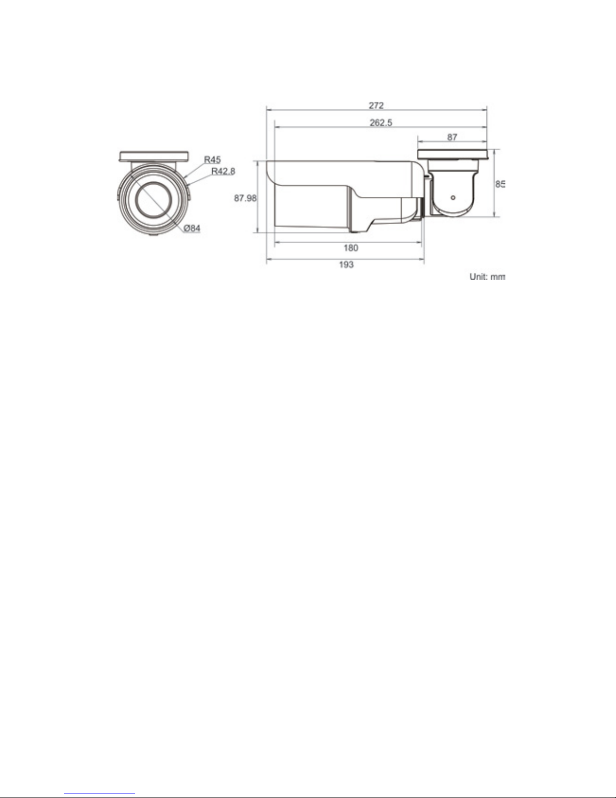
1.3 Dimensions
The IP Camera’s dimensions are shown below.

6
1.4 Connectors
The diagram below shows the IP Dome Camera’s reset button and various connectors.
Denition for each connector will be given as follows.
All-in-one Cable
No Cable Pin Denition Remarks
1Network (with PoE) - RJ-45 connector with LED
2
Power
(3-pin Terminal Block)
1 AC 24V-1 DC (-)
Power connection2 GND Reserved
3 AC 24V-2 DC (+)
3
Alarm
(4-pin Terminal Block)
1 ALM_DI-
Alarm connection
2 ALM_DI+
3 ALM_DO-
4 ALM_DO+
4Audio I/O Pink Line In/ Mic In Two-way audio transmis-
sion
Green Line Out
5BNC - Analog Video Output

7
Micro SD Card Slot / Reset Button
Follow the steps below to reach the Micro SD Card Slot, Reboot Button and Factory
Default Button on IP Camera:
Step 1:
Unscrew the screw on the
Camera Housing and re-
move the Front Housing.
Micro SD Card Slot Factory Default Button Reboot Button
NOTE: Before installing, please refer to Desiccant User Guide in the pack-
age to place the Desiccant in the Camera to prevent moisture from condensing
on IP Camera’s Glass Cover.
8
2. Camera Cabling
Please follow the instructions below to complete IP Camera connection.
2.1 Connect Power
Please refer to Section: Connectors. Alternatively, connect the Ethernet cable to the
camera’s PoE port and plug the other end of the cable into a PoE switch.
NOTE: If using PoE, make sure Power Sourcing Equipment (PSE) is in use
in the network.
2.2 Connect Ethernet Cable
Use of Category 5 Ethernet cable is recommended for network connection; to have best
transmission quality, cable length shall not exceed 100 meters. Connect one end of the
Ethernet cable to the RJ-45 connector of the IP Camera, and the other end of the cable
to the network switch or PC.
NOTE: In some cases, you may need use an Ethernet crossover cable
when connecting the IP Camera directly to the PC.
Check the status of the link indicator and activity indicator LEDs; if the LEDs are unlit,
please check LAN connection.
Green Link Light indicates good network connection.
Orange Activity Light ashes for network activity indication.
2.3 Connect Alarm I/O
The camera equips one alarm input and one relay output for alarm application.
Please refer to the label on the alarm terminal block and connect the alarm wiring ac-
cordingly.
9
3. Installation
Please read the instructions provided in this chapter thoroughly before installing the IP
Bullet Camera.
3.1 Ceiling / Wall Mounting
The IR Bullet IP Camera can be installed directly on a wall or ceiling with the integrated
2-axis adjustable Bracket Mount. Please note that the wall or ceiling must have enough
strength to support the IP Camera.
Follow the steps below to install the IP Camera:
Step 1:
Unpack the IR Bullet IP Camera package and take out the IP Camera.
Step 2:
Connect the power / Ethernet / alarm / audio wires from ceiling or wall to the
corresponding connectors of the camera’s All-in-one Cable.
Step 3:
Fix the IP Camera’s Bracket on the
ceiling / wall with three supplied self
tapping screws.
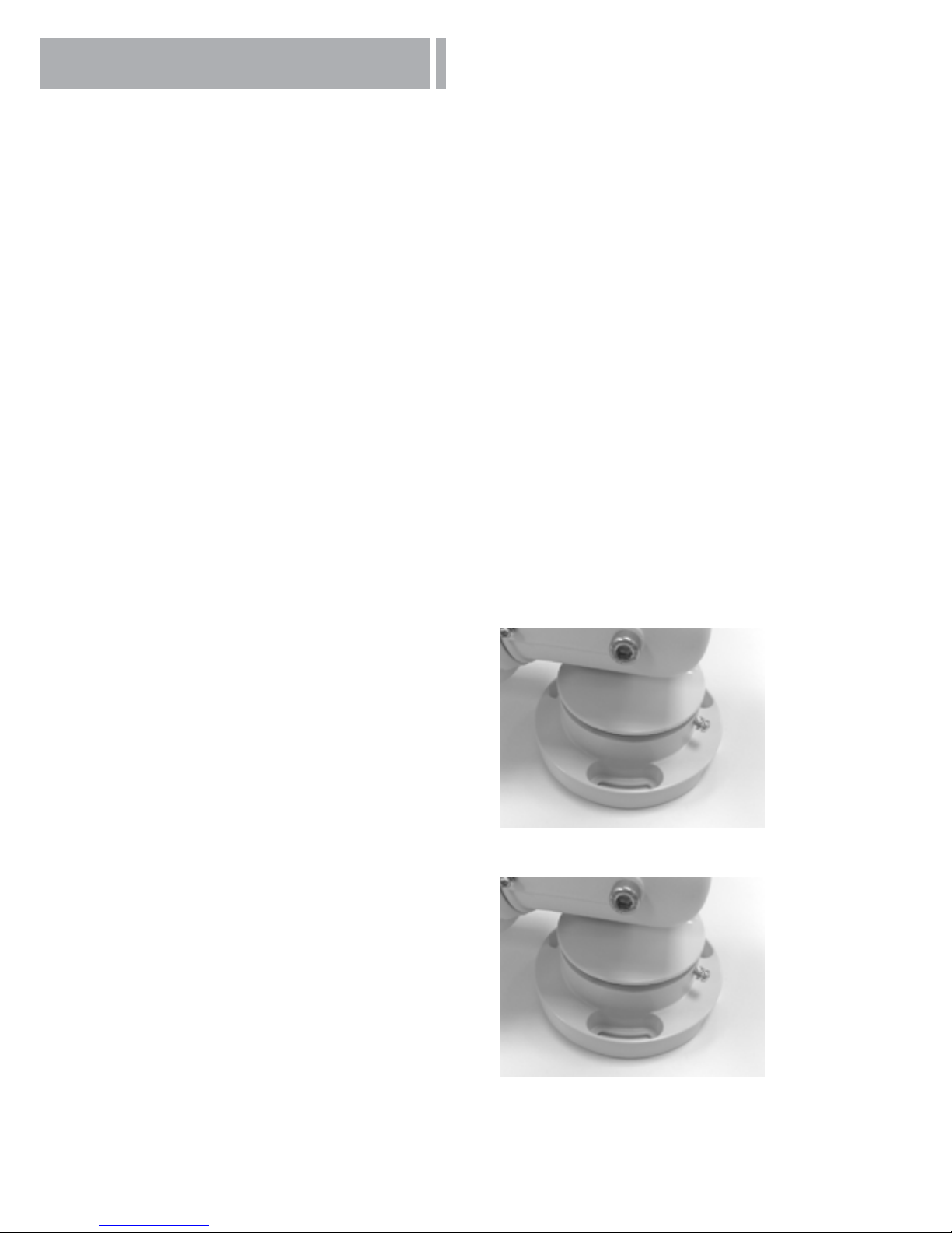
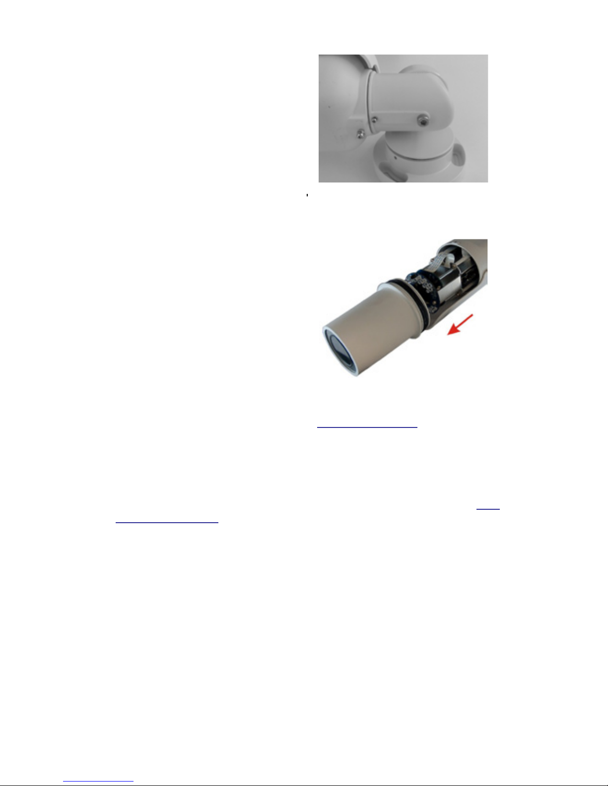
Step 4:
Loosen the screw indicated in the g-
ure, and adjust the camera to a de-
sired position, and tighten the screw
to secure the camera.
10
Step 5:
Use the supplied Inner Hex Wrench
and cross screwdriver to loosen
the hex bolt / screw on the side of
the Bracket Mount and the Camera
Housing to adjust the position of the
IP Camera.
3.2 Lens Adjustment (Vari-focal Lens only)
Step 1:
Unscrew the screw on the Camera
Housing and remove the Front Hous-
ing.
Step 2:
Power up the IP Camera. Please refer to Section: Connectors for more cabling
installing details.
Step 3:
Access the Camera Browser-viewer for viewing images. Please refer to Sec-
tion: Access Camera for further details.
Step 4:
Adjust the Zoom / Focus to set the desired zoom / focal length.
Step 5:
Put the Front Housing back, and make sure it’s well attached to the Camera
Housing, and tighten the screw.
Este manual sirve para los siguientes modelos
1
Tabla de contenidos
Otros manuales de Cámara IP de Centrix


