CDVI A22 Manual de usuario

The installer’s choice
cdvigroup.com
ENGLISH
EN
A22
Web-Based IP 2-Door Hybrid Controller

2cdvigroup.com
EN
ATRIUM A22
2-Door Controller
INSTALLATION MANUAL
EN
ATRIUM A22
2-Door Controller
INSTALLATION MANUAL
Copyright (C) 2011 CDVI. All rights reserved. ATRIUM Access Control is protected by copyright law and international treaties.
Unauthorized reproduction or distribution of this product, or any portion of it, may result in severe civil and criminal penalties,
and will be prosecuted to the maximum extent possible under law.
All other brand and product names are trademarks or registered trademarks of their respective companies.
The information contained in this publication is subject to change without notice.
1] PRODUCT PRESENTATION........................................................3
2] NOTES AND RECOMMENDATIONS..................................................4
FCC & IC Compliance ......................................................... 4
UL Compliance.............................................................. 4
UL 294 Compliance Notice ..................................................... 4
Free Technical Support ........................................................ 4
Recommended Wiring......................................................... 5
Specications .............................................................. 5
3] PACKAGE CONTENTS ............................................................7
Location and Mounting ........................................................ 8
4] MOUNTING INSTRUCTIONS ......................................................9
Installing the Tamper Switches .................................................. 9
Installing the box lock ....................................................... 12
Fixing the Box to its Location .................................................. 13
Installing the A22 PC board ................................................... 14
5] WIRING DIAGRAM .............................................................15
Module type setting (contoller or expander) ........................................ 15
Box Tamper Switches ........................................................ 16
Readers and Keypads ........................................................ 17
Inputs ................................................................. 18
Door Lock Devices .......................................................... 21
Power supply.............................................................. 23
Battery Backup ............................................................ 25
LED Indicators............................................................. 26
Ethernet ................................................................. 27
Expander Modules to the Controller .............................................. 28
6] PROGRAMMING ...............................................................29
Card Enrollment Procedure .................................................... 29
7] WARRANTY - TERMS & CONDITIONS .............................................30
Thank you for buying our products and for
the condence you placed in CDVI.
3
cdvigroup.com
EN
ATRIUM A22
2-Door Controller
INSTALLATION MANUAL
EN
ATRIUM A22
2-Door Controller
INSTALLATION MANUAL
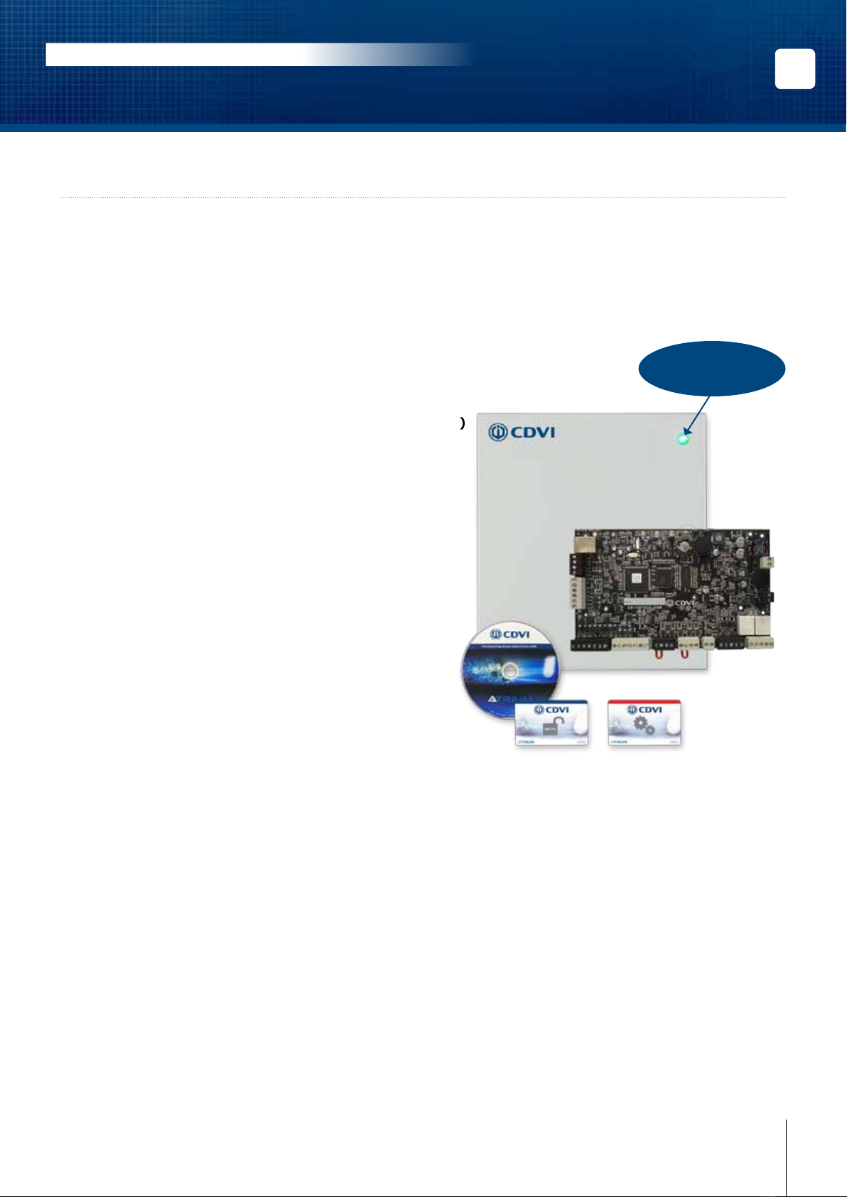
1] PRODUCT PRESENTATION
The A22 is ATRIUM’s powerful Web-Based IP hybrid module. The exibility of the A22 module allows it to be set
either as a 2-door controller or expander (2 in 1). The A22 includes an embedded web server that combines
performance and simplicity enabling you to manage Users/Cards, lock or unlock doors, view system events and
display controller information from any place in the world! Industry-unique and eortless card enrollment mode
minimizes system start up and simplies your life. A pre-assembled universal power supply is included with
every A22 making this unit an industry leader in eciency and simplicity.
• Control 2 doors / 2 readers
• Embedded Web Server
• Pre-assembled universal power supply (120V / 240V)
• On-board Ethernet Port with AES 256-bit encryption
• Auto-detect hardware modules (No DIP Switches)
• Quick and easy card enrollment procedure
• 6 Multi-purpose inputs (12 using zone doubling)
• Totally fuseless system
• Up to 10,000 users
• Up to 10,000 cards
• Up to 25,000 Event Buer
• Up to 100 holidays
• Up to 1000 Access Levels
• Up to 250 Schedules each supporting up to
100 time periods (dd, hh:mm) and recurrence
• Full calendar with leap year support (yyyy-mm-dd)
• Time zone denition (full D.S.T. support)
• 10 Areas per controller
• Ultra fast rmware update (less than 10 seconds)
• FREE Management Software
• Wiegand & ABA Track II magnetic stripe compatible
• Maintenance-friendly snap on terminal connectors
• Comprehensive LED status indicators
Pre-assembled
universal power supply
included

4cdvigroup.com
EN
ATRIUM A22
2-Door Controller
INSTALLATION MANUAL
EN
ATRIUM A22
2-Door Controller
INSTALLATION MANUAL
2] NOTES AND RECOMMENDATIONS
FCC & IC COMPLIANCE
This device complies with Part 15 of the FCC rules Class A. Operation is subject to the following two conditions:
(1) this device may not cause harmful interference, and (2) this device must accept any interference received
including interference that may cause undesired operation. This class A digital apparatus meets all requirements
of the Canadian Interference Causing Equipment Regulations. The ATRIUM A22 is also compliant with
EN55022:1998, amendment 1:1995, Class A.
UL COMPLIANCE
To comply with UL listings, the following requirements must be met:
• Use of UL listed readers (Wiegand: 26-bit, 30-bit and 40-bit; mag stripe: up to 32 digits)
• Use of a UL recognized tamper switch on every housing cabinet for the A22
• Use only UL listed cables
• Use only UL listed adaptors
Note: All circuits are power limited.
UL 294 COMPLIANCE NOTICE
• Use only UL listed power supply
• Connect CDVI LED status indicator, part number 7020-0001-0000, to the DC Input gray terminals of
the A22.
Note: Backup battery provides operation of up to 12 hours but has been tested for 4 hours per
Section 33 of UL 294, fth edition.
The system’s location and wiring methods shall be in accordance with the National Electrical Code,
ANSI/NFPA 70.
FREE TECHNICAL SUPPORT
For technical support in Canada or the U.S., call 1-866-610-0102, Monday to Friday from 8:00 a.m. to 8:00
p.m. EST. For technical support in your area, refer to the last page of this document or visit our website: www.
cdvigroup.com.

5
cdvigroup.com
EN
ATRIUM A22
2-Door Controller
INSTALLATION MANUAL
EN
ATRIUM A22
2-Door Controller
INSTALLATION MANUAL
RECOMMENDED WIRING
SPECIFICATIONS
Equipment Wire Type Size Maximum
Length
Card reader and
Wiegand keypad
4 to 8 conductors, stranded, shielded (foil), drain
conductor. For example: Alpha 5196, 5198, 5386,
5388, Belden 9553
22AWG (0.64mm) to
18AWG (1.02mm) 150m (500ft.)
Zone input 2 conductors, copper 22AWG (0.64mm) 22AWG (0.64mm) 600m (2000ft.)
Door strike 2 conductors, solid copper 18AWG (1.02mm) 18AWG (1.02mm) 150m (500ft.)
Power Supply 3 conductors, solid copper 18AWG (1.02mm) 14AWG (1.63mm)* 8m (25ft.)
Ethernet CAT 5/5e - 100m (300ft)
RS485 bus, Star or
Daisy Chain (no BIAS/
EOL required)
CAT 5/5e or 4 pairs 24AWG (0.51mm)
1220m (4000ft.)
4 conductors, copper 26AWG (0.40mm) to
18AWG (1.02 mm)
* The Minimum Size Equipment Conductors for the AC mains required are 14 AWG if made of Copper or 12
AWG if made of Aluminium or Copper-Clad Aluminium. Do not use any switch-controlled outlets to power the
system.
System Resources
Doors 2 (expandable to 10 doors)
Cards and users Up to 10,000 cards and users
Schedules Up to 250 Schedules each supporting up to 100 time periods (dd, hh:mm)
Buered Events Up to 25,000 events
Holidays Up to 100 holidays (yyyy-mm-dd, hh:mm)
Access Levels Up to 1000 access levels
Operating Temperature -20°C to +70°C (-4°F to +158°F)
Humidity 0% to 85% (non condensing)
System Autonomy Full Distributed Architecture (100% O-line Operation)
Firmware Online Upgradeable
PCB Dimensions 19.9cm (7.83”) x 12.38 cm (4.875”)
Cabinet Dimensions 29 cm (11.4”) high, 28 cm (11”) wide, 8 cm (3.15”) deep
Inputs
Readers 2 x Wiegand Readers with Multiple Protocol Support (Wiegand 26-bit, 30-bit & 44-bit),
Magnetic Stripe ABA Track 2
Keypads 2 x Wiegand Keypad with Multiple Protocol Support (Wiegand 8-bit & 26-bit)
Multi-Purpose Inputs 6 zone inputs (up to 12 using ZONE DOUBLER) with optional individual WIRE CUT &
WIRE SHORT supervision.
Box Tamper Normally Closed (N.C.) contact

6cdvigroup.com
EN
ATRIUM A22
2-Door Controller
INSTALLATION MANUAL
EN
ATRIUM A22
2-Door Controller
INSTALLATION MANUAL
Communication
LOCAL BUS RS485 @ 57600Baud supporting star and/or daisy chain topologies up to 4000ft (1220 meters)
ETHERNET 10/100 Base-T, Auto Sensing, 100m(300ft)
Power Supply
AC Power 120-240Vac
Frequency 50Hz/60Hz
Output 24Vdc, 2.5A
AC Terminal Fuse 250Vac, 2.5 A, Time Lag, Slow Blow, Operating Temperature: -55oC to +125oC
Power Loss Indicator Yes (DC IN)
Do Not Connect to a Receptacle Controlled by a Switch.
Other 24Vac, 75VA 50/60Hz UL/ULC certied transformer can be use.
On-Board Protection (All fuseless, auto-resume)
VLK 12Vdc @ 750mA
AUX 12Vdc @ 1A
Battery Against reversal, short, current limited/monitored
Power output specications
Battery Backup
Battery Capacity 12Vdc 7Ah rechargeable acid/lead or gel cell backup battery (UL/ULC: YUASA #NP7-12
recommended, Europe: CDVI B7AH recommended). Ensure proper polarity.
Charging Current 250mA (default), 320mA, 500mA, or 1A. Refer to the ATRIUM user interface instruction manual
for more information on how to modify the battery charging current.
Low Battery @ 11.8Vdc
Low Battery Restore @ 12.2Vdc
Low Battery Cut-O @ 10.5Vdc
Power Outputs (+12Vdc)
Lock Output 1 Maximum Current 750mA each
Lock Output 2
Reader 1
Maximum Current 1000mA
Reader 2
Zone Inputs
LOCAL BUS
Outputs
LK1, LK2, RLY1, RLY2 Form C Relay, 5A @ 250Vac, 7A @ 125Vac, 7A @ 30Vdc

7
cdvigroup.com
EN
ATRIUM A22
2-Door Controller
INSTALLATION MANUAL
EN
ATRIUM A22
2-Door Controller
INSTALLATION MANUAL
3] PACKAGE CONTENTS
This chapter details how to install and setup the ATRIUM A22 .
The A22 contains:
• One A22 module in its cabinet with connection diagram label
• AC power cord
• Metal Box kit (See below)
• Installation kit (See below)
Metal Box
Kit
Wall Switch
and a white
wire (115mm)
3 wires for
tamper switch
(2 x 360mm
and
1 x 165mm)
Bolts and Nuts Wall Switch
Spacer
Door Switch
and 2 white
wires
(350mm)
Door Switch
Support
Metal box
screw for door
enclosure
Metal box
lock and key
1 3 2 each 1 1 1 4 1
Installation
Kit
Red and black
wires, for
backup battery
(400mm)
1K Resistor 2.2K Resistor
Diode 1N4007
for DC door
strikes or
maglocks
Varistor for AC
door strikes or
maglocks
Fastener
(PCB Holder)
1 pair 22 10 2 2 7
If any item is missing, please notify your distributor immediately.

8cdvigroup.com
EN
ATRIUM A22
2-Door Controller
INSTALLATION MANUAL
EN
ATRIUM A22
2-Door Controller
INSTALLATION MANUAL
LOCATION AND MOUNTING
The cabinet is designed to be installed indoors, in a safe and secure location. Suggested locations include
electrical rooms, communication equipment rooms, closets or in the ceiling. To save time, wiring and facilitate
testing, install the cabinets at an equal distance between its controlled doors. Normal temperature and humidity
levels should be maintained.
Please note that other approved cabinets with approved tamper switch on the front cover and rear
surface can be used.
Cabinet Dimensions:
29 cm (11.4”) high, 28 cm (11”) wide, 8 cm (3.15”) deep
The Cabinet Can Accommodate:
One 12Vdc @ 4.5AH or 7AH, gel cell type batteries and wiring connections (15cm (6”) high,
6cm (2.5”) wide, 9 cm (3.54”) deep)
Battery Model Voltage Capacity Length Width Height
YUASA #NP7-12 12 Volt 7 Ah 151mm (5.94”) 65mm (2.56”) 97.5mm (3.84”)
YUASA #NP4-12 12 Volt 4.5 Ah 90mm(3.54”) 70mm (2.76”) 106mm (4.17”)
Multiple Conduit Knock-outs:
Two 19.05mm (0.75”) on each side and one 12.7mm (0.5”) on top
Minimum Clearance For Cabinet:
25cm (10”) clear space around all sides
38cm (15”) clear space in front of cabinet
Minimum Clearance From Electrical Interference:
2.4m (8ft.) from high voltage equipment or wiring and from electrical equipment likely to
generate interference
1.2m (4ft.) from telephone equipment or lines and 8m (25ft.) from transmitting equipment
The system’s location and wiring methods shall be in accordance with the National Electrical Code,
ANSI/NFPA 70.

9
cdvigroup.com
EN
ATRIUM A22
2-Door Controller
INSTALLATION MANUAL
EN
ATRIUM A22
2-Door Controller
INSTALLATION MANUAL
4] MOUNTING INSTRUCTIONS
The box needs to be prepared before xing it to its location.
INSTALLING THE TAMPER SWITCHES
Installing tamper switches allows the A22 to detect when the cabinet door is opened and/or when the cabinet is
removed from the wall. If needed install the tamper switch(es) as follows:
Metal box
holes where
to x the wall
tamper switch

10 cdvigroup.com
EN
ATRIUM A22
2-Door Controller
INSTALLATION MANUAL
EN
ATRIUM A22
2-Door Controller
INSTALLATION MANUAL
Cabinet Side View
Cabinet Door
Nut
Spacer
Spacer
Screw
Spacer
Install the wall tamper switch using the supplied bolts and nuts as shown in the following picture.
Install the tamper switch
plastic spacer on the back
at bottom left side of
the box as show in
the following picture.
Este manual sirve para los siguientes modelos
1
Tabla de contenidos
Otros manuales de Controladores de CDVI

CDVI
CDVI SASIC Manual de usuario

CDVI
CDVI ATRIUM A22K Manual de usuario

CDVI
CDVI DG502U/A Manual de usuario

CDVI
CDVI ATRIUM AC22 Manual de usuario

CDVI
CDVI ATRIUM A22POE Manual de usuario

CDVI
CDVI STAR1M Manual de usuario

CDVI
CDVI ATRIUM A22K Manual de usuario

CDVI
CDVI ATRIUM A22K Manual de usuario

CDVI
CDVI PROMI1000PC Manual de usuario

CDVI
CDVI SOLAR2R Manual de usuario


